background image

28

Configuring the Access Point

Configuring for Standalone Operation or for Management by FlexMaster

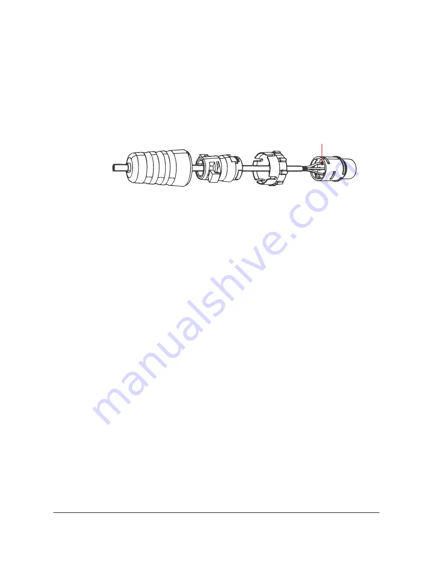
Figure 23.

Insert the conductors into the pins, crimp or solder the edges, and then 
insert the pins into the connector

7.

Push the coupling ring all the way forward so that it covers the edge of the cord 
connector.

8.

Push the cable clamp housing forward until it locks into the connector body. The two 
clamps should snap into their compartments.

9.

Push the boot all the way forward so that it covers the cable clamp housing securely.

10.

Remove the protective cap from the 12V DC connector on the AP.

11.

Connect the DC cord connector that you have assembled to the 12V DC connector on 
the AP.

12.

Connect the DC cable to a DC power source (for example, a battery).

You have completed connecting the Access Point to the administrative computer and to 
a DC power source.

Step 3: Log In to the Access Point’s Web Interface

1.

On the administrative computer, open a Web browser window.

2.

In the address or location bar, type the following address:

https://192.168.0.1

3.

Press 

<Enter>

 on the keyboard to connect to the Access Point’s Web interface. A 

security alert message appears.

4.

Click 

Yes

 or 

OK

 (depending on the browser) to continue. The Access Point’s login page 

appears.

Crimp or solder the conductors 

before inserting them into the 

connector

Содержание ZoneFlex 7762-S

Страница 1: ...Ruckus Wireless ZoneFlex 7762 S Dual Band 802 11n Smart Wi Fi Outdoor Sector Access Point Installation Guide Part Number 800 70293 001 Rev B Published April 2011 www ruckuswireless com...

Страница 2: ......

Страница 3: ...on and Positioning 9 Physical Obstructions and Sources of Interference 9 Sector Coverage and Recommended Downtilt 10 360 Coverage of Deployment Area 12 Become Familiar with the Installation Components...

Страница 4: ...eck the TR069 Status FlexMaster Management Only 38 Disconnect the Access Point from the Network 38 6 Deploying the Access Point 39 Step 1 Connect and Seal the RJ 45 Cable 39 Step 2 Complete the Power...

Страница 5: ...iii 10 Resetting the Access Point to Factory Default Settings 59 11 What to Do Next 63 Change the Administrative Password 63 Configure the Security Settings 63 Read Related Documentation 63...

Страница 6: ...iv...

Страница 7: ...kuswireless com documents Release Notes Provides late breaking information about the current software release including new features enhancements and known issues If the information in the Release Not...

Страница 8: ...lastic bag containing the Ruckus Wireless PoE injector for ZoneFlex 7762 S AP Box containing the power adapter for the PoE injector Box containing the mounting kit see Mounting Kit Contents for detail...

Страница 9: ...nts Figure 1 DC connector pins and DC cord connector assembly Figure 2 RJ 45 waterproofing assembly Boot DC cord connector Coupling ring Connector pins 4 pieces Cable clamp housing RJ 45 connector on...

Страница 10: ...et Static bracket Steel clamp 2 pieces Machine screws 8 pieces Hex bolts 4 pieces Flat washers 4 pieces Split lock washers 4 pieces Wall anchors 4 pieces Figure 4 Mounting kit contents Dynamic bracket...

Страница 11: ...nents Decide How You Will Supply Power to the Access Point Prepare the Required Hardware and Tools You must supply the following tools and equipment A notebook computer running Windows 7 Vista XP 2000...

Страница 12: ...es that are relevant to the installation and mounting instructions that this guide provides Before you begin the installation process Ruckus Wireless recommends that you become familiar with these fea...

Страница 13: ...ng is disabled but the WLAN service is available the Status LED is also green Fast flashing green The AP is part of a mesh network as Mesh AP and is connected to an uplink with a fair or good signal S...

Страница 14: ...GHz External Antennas on page 56 Figure 6 The 5GHz antenna connectors are protected by metal caps DC Connector In addition to PoE you can also use direct current or DC from a battery for example to su...

Страница 15: ...terference Physical obstructions such as concrete pillars steel beams filing cabinets buildings or trees can block or hinder wireless communication For more Access Point placement guidelines refer to...

Страница 16: ...ts 2 4GHz radio To enable the AP to cover its immediate area effectively and at the same time extend its wireless coverage farther using this radio Ruckus Wireless recommends mounting the AP in a vert...

Страница 17: ...11 Before You Begin Determine the Optimal Mounting Location and Positioning Figure 8 The 7762 S provides a 120 horizontal beamwidth 120 horizontal beamwidth...

Страница 18: ...ocated APs to provide a 360 degree area of coverage make sure you read Connecting Colocated 7762 S Access Points on page 14 Become Familiar with the Installation Components The Access Point can be ins...

Страница 19: ...hat is attached to the Access Point form the drip loop near the AP This will prevent water from running along the cable and entering the Access Point Also add a second drip loop at the point of entry...

Страница 20: ...er and can be connected to both power sources at the same time If you connect the Access Point to both PoE and DC power sources at the same time it will use 12V DC power as the primary power source an...

Страница 21: ...fore You Begin Connecting Colocated 7762 S Access Points Figure 11 Colocated 7762 S APs connected separately to the same outdoor Ethernet switch Outdoor Ethernet switch Three colocated 7762 S APs Inte...

Страница 22: ...efore You Begin Connecting Colocated 7762 S Access Points Figure 12 Colocated 7762 S APs connected separately to the same indoor Ethernet switch Internet Indoor Ethernet switch Three colocated 7762 S...

Страница 23: ...ery to enable the Access Point to register with ZoneDirector you can also use DHCP Option 43 or DNS For more information refer to the ZoneDirector User Guide Before starting this procedure check the b...

Страница 24: ...nd DC power in your final deployment Use Power Over Ethernet 1 Take out the PoE injector and the power adapter from the Access Point package 2 Obtain two Cat5e or better Ethernet cables 3 Connect one...

Страница 25: ...on the length Total round trip resistance must be less than 0 4 ohm This means no more than seven meters of 20 gage copper The insulation should comply with local code requirements Make sure that the...

Страница 26: ...part of the conductors into the four connector pins and then crimp the edges of the connector pins to secure the conductors Alternatively use a soldering gun to solder the conductors to the pins 5 In...

Страница 27: ...to the connector body The two clamps should snap into their compartments 8 Push the boot all the way forward so that it covers the cable clamp housing securely 9 Remove the protective cap from the 12V...

Страница 28: ...n the same row as the Access Point s MAC address This allows the Access Point to register with ZoneDi rector When the Status column shows Connected this indicates that the Access Point has successfull...

Страница 29: ...00 If you are using a different operating system refer to the documentation that was shipped with your operating system for information on how to modify the computer s IP address settings 1 On your Wi...

Страница 30: ...close the TCP IP Properties dialog box 7 Click OK again to close the Local Area Connection Properties dialog box Windows saves the IP address settings that you have configured Figure 18 Sample config...

Страница 31: ...cables 3 Connect one end of one Ethernet cable to the AP BRIDGE port on the PoE injector and then connect the other end to the PoE IN port on the Access Point 4 Connect one end of the other Ethernet c...

Страница 32: ...de requirements Make sure that the cable that is long enough to connect the AP at its mounting location with the DC power source A pair of long nose pliers A soldering gun optional To assemble the DC...

Страница 33: ...nector pins and then crimp the edges of the connector pins to secure the conductors Alternatively use a soldering gun to solder the conductors to the pins 6 Insert all four connector pins into the hol...

Страница 34: ...rom the 12V DC connector on the AP 11 Connect the DC cord connector that you have assembled to the 12V DC connector on the AP 12 Connect the DC cable to a DC power source for example a battery You hav...

Страница 35: ...plete this step you will need to configure the settings on the Common tab and at least one Wireless tab These are the essential wireless settings that will enable wireless devices on the network to as...

Страница 36: ...to Wireless 8 8 WLANs Encryption security Disabled on all WLANs Default management IP address 192 168 0 1 Table 4 Common wireless configuration Setting Recommended Value Wireless Mode Auto select Chan...

Страница 37: ...31 Configuring the Access Point Configuring for Standalone Operation or for Management by FlexMaster...

Страница 38: ...s network For example you can type Ruckus Wireless AP This SSID is the name that will help users identify this wireless network in their wireless network connection applica tion NOTE You may also conf...

Страница 39: ...For more information refer to the FlexMaster User Guide 1 On the menu click Administration Management 2 Scroll down the page to the TR069 SNMP Management Choice section 3 Verify that the Auto option i...

Страница 40: ...le device for example another ZoneFlex 7762 S AP or an IP based surveillance camera The PoE feature for the PoE OUT port needs to be enabled from the Web interface NOTE If you use DC power or a PoE in...

Страница 41: ...ss Point from the power source either from the PoE injector or DC power source 2 Verify that the PWR LED on the back of the Access Point is off 3 Disconnect the Ethernet cable from the administrative...

Страница 42: ...the scrolling list and then click Properties The TCP IP Properties dialog box appears 4 Restore the computer s network settings by typing the original IP address settings in the TCP IP Properties dial...

Страница 43: ...ernet cable from the PoE IN port on the Access Point to your network s router or switch 2 Connect the DC cable to a DC power source You have completed connecting the Access Point to your live network...

Страница 44: ...FlexMaster server You can do this by checking the TR069 status on the Access Point s Web interface 1 Log in to the Access Point s Web interface 2 Go to the Administration Management page 3 Scroll dow...

Страница 45: ...aterproof connector assembly 2 Feed the end of the RJ 45 cable through the sealing nut rubber O ring and clamping ring assembly in the same order See Figure 29 Figure 29 RJ 45 waterproof connector ass...

Страница 46: ...ns on completing the power connection that you need to make refer to the procedures below Use Power Over Ethernet Use DC Power Use Power Over Ethernet 1 Take out the PoE injector and the power adapter...

Страница 47: ...Access Point Step 2 Complete the Power Connections Figure 30 Connect the Ethernet cables and power adapter to the PoE injector You have completed setting up the PoE power connection To AP To network T...

Страница 48: ...pair of long nose pliers A soldering gun optional To assemble the DC cord connector and supply DC power to the AP 1 Connect one end of an Ethernet cable to the PoE IN port on the AP and then connect t...

Страница 49: ...then crimp the edges of the connector pins to secure the conductors Alternatively use a soldering gun to solder the conductors to the pins 6 Insert all four connector pins into the holes on the cord c...

Страница 50: ...DC cable to a DC power source for example a battery You have completed connecting the Access Point to the administrative computer and to a DC power source WARNING Do not apply power to the Access Poi...

Страница 51: ...e AP is connected to the AP BRIDGE port on the PoE injector 5 Connect the Ethernet cable from the NETWORK port on PoE injector to your network router or switch 6 Apply power to the Access Point If you...

Страница 52: ...le Two steel clamps supplied with the AP 10mm flathead screwdriver Step 1 Attach the Static Bracket to the Mounting Surface The procedure for attaching the bracket to the mounting surface depends on w...

Страница 53: ...ations of the mounting holes o 3 Remove the static bracket from the mounting surface 4 Drill an 8mm diameter hole with a depth of 36mm 38mm into each of the four markings that you made on the mounting...

Страница 54: ...rque value must be 0 4 0 5 Newton meter Nm As you tighten the nuts the metal cones that are built into the wall anchors will expand and lock the wall anchors into place 10 Continue to Step 2 Attach th...

Страница 55: ...49 Attaching the Mounting Brackets Step 1 Attach the Static Bracket to the Mounting Surface Figure 38 Insert the steel clamps into the two tabs on the bracket...

Страница 56: ...0 Attaching the Mounting Brackets Step 1 Attach the Static Bracket to the Mounting Surface 3 Use the clamps to attach the bracket to the pole Figure 39 Use the clamps to attach the bracket to the pole...

Страница 57: ...cket 5 Continue to Step 2 Attach the Dynamic Bracket to the Access Point Step 2 Attach the Dynamic Bracket to the Access Point 1 Place the dynamic bracket onto the flat side of the Access Point so tha...

Страница 58: ...ynamic Bracket to the Access Point 3 Using a 6mm Phillips screwdriver tighten the four machine screws to fasten the bracket to the Access Point Screw torque value must be 0 4 0 5 Newton meter Nm 4 Con...

Страница 59: ...e or horizontal surface are similar To join the two mounting brackets together 1 Join the two brackets as shown in Figure 41 Make sure that The dynamic bracket attached to the Access Point encloses th...

Страница 60: ...on the static bracket 3 Place a split lock washer and then a flat washer onto a hex bolt Then insert the hex bolt into one of the mounting holes NOTE Make sure the screw washer assembly is in correct...

Страница 61: ...desired orientation NOTE If you have not yet determined the optimal orientation for your Access Point refer to Determine the Optimal Mounting Location and Positioning on page 9 for orientation guideli...

Страница 62: ...fe place in case you need them later 3 Connect the 5GHz antennas to the standard N type female antenna connectors on the Access Point If the 5GHz antennas come with RF coaxial cables for example a pat...

Страница 63: ...mmand line interface 2 Set the 5GHz antenna gain by entering the following command set extantgain wifi name 0 90dBi 3 Verify that the antenna gain has been configured by entering the following command...

Страница 64: ...must be enabled before you can configure the antenna gain 6 Select the check box after External Antenna and then enter the antenna gain value in dBi in the box provided 7 Click OK at the bottom of th...

Страница 65: ...t that is provided with the Access Point package to perform this procedure NOTE The Access Point can only be reset to factory default if it is using PoE 1 Verify that the Access Point is using PoE as...

Страница 66: ...60 Resetting the Access Point to Factory Default Settings Configuring the 5GHz Antenna Gain 4 Install the shunt on pins 3 and 4 as shown in Figure 45 Figure 45 Install the shunt Pin 3 Pin 4...

Страница 67: ...61 Resetting the Access Point to Factory Default Settings Configuring the 5GHz Antenna Gain 5 Wait 10 seconds and then remove the shunt Figure 46 Wait 10 seconds Figure 47 Remove the shunt...

Страница 68: ...Settings Configuring the 5GHz Antenna Gain 6 Verify that the STATUS LED on the Access Point is off If the STATUS LED is off it indicates that the reset process is complete You have completed resetting...

Страница 69: ...to compromise your network Configure the Security Settings Unlike wired networks anyone with a compatible wireless adapter can receive wireless data transmissions from your network well beyond your wa...

Страница 70: ...64 What to Do Next Read Related Documentation...

Отзывы: