background image

www.rslogger.com


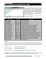
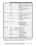
[UART_A]

BAUDRATE_A

115200

Channel A UART port baudrate  setting. Range [128 – 
230400] 

DATABITS_A

8

Channel A UART port data bits setting. Values: 7, 8, 9
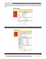
 Please refer to comments at the bottom of this page!

PARITY_A

0

Channel A UART port parity  setting. 
0 – no parity
1 – even parity 
2 – odd parity.       Please refer to comments!

STOPBITS_A

1

Channel A UART port stop bits setting. 
1 - (one stop bits)
2 -  (two stop bits)

[UART_B]

BAUDRATE_B

115200

Channel B UART port baudrate setting. Range [128 – 
230400] 

DATABITS_B

8

Channel B UART port data bits setting. Accepted 
values: 7, 8, 9  Please refer to comments!

PARITY_B

0

Channel B UART port parity  setting. 
0 – no parity
1 – even parity 
2 – odd parity.        Please refer to comments!

STOPBITS_B

1

Channel B UART port stop bits setting. 
1 - (one stop bits)
2 -  (two stop bits)

[VIRTUALCOM]

VIRTUALCOMMODE

3

Virtual COM feature mode. 
0 – disabled
1 – Channel A data forwarding
2 – Channel B data forwarding
3 – Terminal text menu mode
4 – AT commands interface
5 – Channel A+B data forwarding (raw mixed)

[ETHERNET]

HOSTNAME

rslogger

Device Host name for LAN.

IP

192.168.1.100

Device’s IP address. 

MASK

255.255.255.0

IP address mask.

GATE

192.168.1.1

LAN Gateway IP address.

TCOM1MODE

0

TCP COM1 port mode:
0 – disabled
1 – Channel A data forwarding
2 – Channel B data forwarding

TCOM1PORT

22334

TCP port number for TCP COM1

TCOM2MODE

0

TCP COM2 port mode:
0 – disabled
1 – Channel A data forwarding
2 – Channel B data forwarding

TCOM2PORT

22335

TCP port number for TCP COM2

Comments:

  according to RS232 data frame format the  databits and parity  settings are related. Some abnormal

combinations of these parameters are forced or prohibited. For example: for databits = 7 the parity have to be always
enabled (odd or even) and for databits =9 the parity has to be always disabled (parity = 0).

 24                                                                                                                                                  © 

Electroware

 2018

Содержание Basic

Страница 1: ...RSLogger Users Manual Ver 1 30 Electroware 2018 www rslogger com ...

Страница 2: ... Text Menu mode for settings and AT commands for data download remote control RS232 ports forwarding splitting mode to Virtual COM USB or Ethernet TCP output Advanced Date Time stamping date as a file name 1ms precision time stamps rechargeable RTC backup battery built in smart recharge circuit OLED 128x64 display for actual device status Always up to date with secure firmware update feature and b...

Страница 3: ... actual connection status on OLED display RSLogger Basic front panel USB A connect your USB Mass Storage here for on demand data download automatic backups or left unconnected LED1 USB Mass Storage status indicator Avoid disconnecting of the Mass Storage during read write operation LED1 on when Mass storage connected LED1 blinks while read write LED1 off when no drive detected RS232 DSub RS232 cha...

Страница 4: ...r supply port accepts 5 to 28V DC GND RS232 ground and power ground both GND pins are shorted AUX auxiliary line GPIO port for additional control connected with push button feature LED 1 USB Mass Storage status indicator Avoid disconnecting of the Mass Storage during read write operation LED1 on when Mass storage connected LED1 blinks while read write LED1 off when no drive detected LED 2 system s...

Страница 5: ...nd GPIO2 functionality for RSLogger module is the back to factory default function described in the Back to factory default firmware settings chapter RED LED indicator USB Mass Storage status indicator Avoid disconnecting of the Mass Storage during read write operation LED ON when Mass storage connected LED blinks while read write LED OFF when no drive detected GREEN LED indicator system status in...

Страница 6: ...ice is already set up to meet your installation requirements it s ready to record RS232 data Connect the RS232 cable or cables and power it on RSLogger may act as an end point device to record the RX stream from one RS232 device only or can be installed in between RS232 transmitter and receiver devices to record both side communications RX TX Please refer to Extracting the data chapter for availab...

Страница 7: ...asy folders sorting Header is followed by 6 bytes long serial number in HEX format like 120004 From now on it s the logger s main operating folder It s the home for iall data settings and system configuration files Unique folder name for every single RSLogger allows to use one Mass Storage drive to handle several different RSLoggers Each device has it s own directory named by it s unique serial nu...

Страница 8: ...the PASSWORD TXT text file would be created in devices folder after new setting applying Please keep the password file on the USB mass storage inside the device folder as long as you want to get access to your protected device with this particular Mass Storage device it s containing the password string USB mass storage devices without actual PASSWORD TXT file located in the device folder would not...

Страница 9: ...Br y applications with RSLogger s text menu Please refer to the Virtual COM terminal text menu mode chapter for more details about using the text menu Via Ethernet On Ethernet enabled devices it s possible to download data from WWW interface Any Internet browser can be used PC or mobile device connected to the same LAN Enter the http rslogger as a domain or it s IP number directly if known method ...

Страница 10: ...sword as both user and password to not to mismatch the device s passwords All device s settings may be managed by two menu optios Logger Settings and Network Settings Network Settings menu IP address settings DHCP enable WWW Password TCP Virtual COM ports settings Logger Settings menu time set timestamp log file mode RS232 log port A B settings baud parity etc 10 Electroware 2018 ...

Страница 11: ...YMMDDCC TXT format Y ear M onth D ay C hannel just like following example 170626AB TXT MEMORY MAP system file is keeping the actual index information which internal circular buffer sectors currently in use were already downloaded to the backup USB Mass Storage It s to avoid data duplication or data overlapping in the downloaded text files Deleting the MEMORY MAP file will result in index reset Ent...

Страница 12: ...ory dumps to USB Mass Storage would be executed automatically in the background task every minute creating the intelligent up to date continuous backups Buffer memory itself is capable to keep up to 128MB of formatted data including precise time stamps channel indicators etc Although the internal memory itself is capable to hold months of regular RS232 communication permanent or at least periodica...

Страница 13: ...ile browsers RSLogger s WWW data download page Navigate to the LOG menu allowing you to download the data from the internal memory buffer Select the request date range and apply it by Set Data Range button Read Log button would be activated then press it to search and download the data from requested date range It would take a while to dowlnoad the data please wait The current status would be disp...

Страница 14: ...header containing precise time stamp and channel indicator tabulation and then followed by new line n Same example bytes XyZ123 recorded below Channelmode 1 Timestamp 1 File 170626AB TXT P 5 59 59 123A X P 5 59 59 125B y P 5 59 59 127B Z P 5 59 59 128A 1 P 5 59 59 129A 2 P 5 59 59 130B 3 ASCII binary in separated channel files A and B raw data form both A and B channels are stored in two linear te...

Страница 15: ...B data A1 02 47 431A Channel A data Option Timestamp delay available for CHANNELMODE 1 and CHANNELMODE 2 Delay 1000 S where S is delay expressed in seconds range of 1 43200 Time stamps marks maximum frequency is set by delay parameter Timestamp would appear every S seconds corrected by the actual data byte ms precision timestamp Timestamps are asynchronous for channel A and B CHANNELMODE 2 Time st...

Страница 16: ...e Type the password and it confirm with Enter key Main Menu should be displayed as follows MENU 1 SysInfo 2 File 3 DateTime 4 UART A 5 UART B 6 VirtualCOM e Exit MENU File Back 1 Password 2 Timestamp 3 Channel Mode MENU File Channel Mode Back 1 One Common file for Both A and B channels 2 Two separated files for A and B channels ChannelMode 1 Navigate the menu options as you like using your 0 9 key...

Страница 17: ...d in the real time as it s depending on the RS232 data rate and actual LAN traffic and topology TCP Virtual COM Ports may be set with WWW interface or CONFIG INI file be editing the ETHERNET section parameters TCOM1MODE and TCOM2MODE to one of the proper values 0 to disable the Virtual COM port default 1 for RS232 channel A data forwarding 2 for RS232 channel B data forwarding and the correspondin...

Страница 18: ...the data from B channel no TimeStamp RDAY_ABT password yyyy mm dd Read data from specific day both channels A B with TimeStamp RDAY_AT password yyyy mm dd Read data from specific day both channel A with TimeStamp RDAY_BT password yyyy mm dd Read data from specific day both channel B with TimeStamp RDAY_AB password yyyy mm dd Read data from specific day both channels A B no TimeStamp RDAY_A passwor...

Страница 19: ...r You can use sevral different USB Mass Storage devices to download the data from same logger connected in different time Deleting the MEMORY MAP file will result in backup map erasing and all available data from internal memory would be considered as new data ready to be saved in the text file form again Please notice that without MEMORY MAP file some logged data may get permanently lost would no...

Страница 20: ... accomplished successfully for example due to the power failure There are three ways for firmware update and two of them are available for the end users Update with USB Mass Storage simply store the firmware file on the USB Mass Storage device used for data download password labeled and connect it to the RSLogger device If the FIRMWARE BIN file has been found on the connected USB mass storage driv...

Страница 21: ...be disabled no password protection For RSLogger Module devices there is no push button installed but the back to default firmware feature is still available with GPIO1 and GPIO2 ports located on the device s main terminal Pelase short the GPIO1 to GPIO2 when the device is powered off Turn on the RSLogger Module power and then after 5 seconds remove the GPIO1 GPIO2 jumper The back to factory defaul...

Страница 22: ...river properties if disabled otherwise FTDI chip would not be visible as a standard serial COM Port but as a USB device only FTDI USB Serial Converter device on Windows Device Manager list and it s advanced properties for VCP module loading Restart the device after changing the VCP mode in driver settings to load the virtual com port module Additional new device USB Serial Port should be found in ...

Страница 23: ...ory upon next power up or USB Flash Mass storage connection FILE PASSWORD RSLOGGER123 USB Flash drive password label Blank by default TIMESTAMP 0 0 disable 1 Enabled for every byte 2 Enabled for active channel switch only CHANNELMODE 1 1 one common file for both A and B channels 2 two separated files for A and B channels DATAFORMAT 0 0 ASCII binary 1 HEX DATETIME SETDATE SETDATE 2018 01 01 Date se...

Страница 24: ...TUALCOM VIRTUALCOMMODE 3 Virtual COM feature mode 0 disabled 1 Channel A data forwarding 2 Channel B data forwarding 3 Terminal text menu mode 4 AT commands interface 5 Channel A B data forwarding raw mixed ETHERNET HOSTNAME rslogger Device Host name for LAN IP 192 168 1 100 Device s IP address MASK 255 255 255 0 IP address mask GATE 192 168 1 1 LAN Gateway IP address TCOM1MODE 0 TCP COM1 port mod...

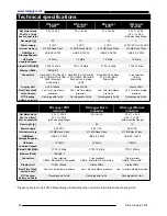
Страница 25: ...precision Yes 1ms time stamp precision RTC backup battery on board Rechargeable 2mAh Rechargeable 2mAh Rechargeable 2mAh Rechargeable 2mAh RSLogger PRO Industrial RSLogger Basic Industrial RSLogger Module Industrial Net dimensions W x H x L mm incl connectors 22 x 11 x 24 5 22 x 11 x 28 5 with mounting flange 55x16 x55 22 x 11 x 24 5 22 x 11 x 28 5 with mounting flange Net weight g 70 65 10 Power ...

Страница 26: ...www rslogger com See more on www rslogger com page DEALER CONTACT 26 Electroware 2018 ...

Отзывы: