
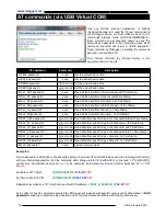

www.rslogger.com
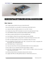
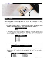
RSLogger Basic
rear panel
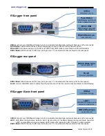
Micro USB:
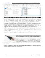
main power supply port (5VDC) and USB Virtual COM mode communication via Micro USB cable.
RS232 DSub:
RS232 channel B (TX) input (all 9 pins are 1:1 connected with channel A port at the front panel)
Push Button:
hidden button enables the one-click back to factory firmware (when pressed at power up for 5s).
LED 2:
system status indicator for devices without OLED display. LED2 is on as power-on indicator, LED2 blinks fast
while actual RS232 data recording to internal flash memory, LED2 blinks during back to default reset procedure.
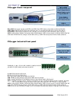
RSLogger Industrial
front panel
Detachable, 6-ways, 3.5mm pitch standard industrial terminal
connector for direct and secure wires connection:
A:
RS232 link channel A (TX) input
B:
RS232 link channel B (RX) input
Vcc:
main power supply port (accepts 5 to 28V DC)
GND:
RS232 ground and power ground (both GND pins are shorted)
AUX:
auxiliary line/GPIO port for additional control (connected with push button feature)
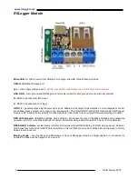
LED 1:
USB Mass Storage status indicator. Avoid disconnecting of the Mass Storage during read/write operation!
LED1 on when Mass storage connected, LED1 blinks while read/write, LED1 off when no drive detected.
LED 2:
system status indicator for devices without OLED display. LED2 is on as power-on indicator, LED2 blinks fast
while actual RS232 data recording to internal flash memory, LED2 blinks during back to default reset procedure.
USB-A:
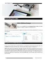
connect your USB Mass Storage here for on-demand data download, automatic backups or left unconnected.
4 ©
Electroware
2018
Micro USB
5VDC power supply and
Virtual COMoperations
LED 2
system status indicator
Push Button
device control and
back to default function
RS232 DSub 9-pin
input channel B
LED 1 & 2
system status indicators
RS232: RX, TX, GND
GND, Vcc, Aux
USB-A
USB Mass Storage