15
S - SPECIAL OR CRITICAL USERS INSTRUCTIONS - SAR
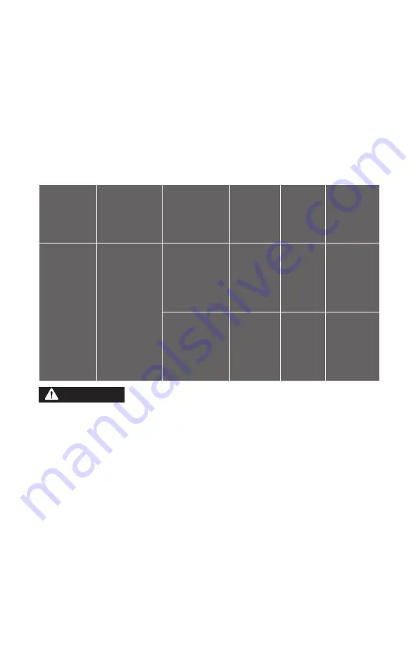
TABLE 1.1
This table lists Air pressure ranges needed to provide the RPB
®
Z-LINK
®
with the volume
of air that falls within the required range of 170 - 425 slpm (6 -15 cfm) according to
GOVERNMENT REGULATIONS. Maximum working pressure of the compressed air supply
tube is 20.7 BAR.
BREATHING AIR PRESSURE TABLE
Make sure you understand the Breathing Air Pressure table before
using this respirator.
1.
Use the correct air source. Do not use an ambient air pump, as it does not supply enough
pressure (column 1).
2.
Confirm the part number of the air supply hose (column 2) and the flow control device
(column 3) you are using.
3.
Check your RPB
®
Safety Air Supply Hose is within the correct length (column 4) and the
correct number of hose sections (column 5).
4.
Set the air pressure at the point of attachment within the range specified (column 6).
Make sure air is flowing through your respirator when setting the air pressure.
Failure to supply the minimum required air pressure at the point of attachment for the length
of air supply hose will decrease the level of protection provided. Check that the capacity
of the air supply systems can provide sufficient air to all users, with a maximum of 5 users
connected simultaneously per air supply unit. In addition, could result in contaminants being
inhaled as the pressure in the helmet may become negative due to peak inhalation flow when
working at very high work rates. Low airflow will decrease the level of protection provided.
ALWAYS WEAR EAR PLUGS WHEN WEARING THIS APPARATUS.
WARNING
1. AIR SOURCE
2. AIR SUPPLY
HOSE
3. FLOW
CONTROL
DEVICE USED
WITH 04-835
BREATHING
TUBE ASSEMBLY
4. SUPPLY
HOSE
LENGTH
(METRES)
5. MAX
NUMBER
OF
SECTIONS
6. PRESSURE
RANGE
(BAR)
PORTABLE OR
STATIONARY
COMPRESSOR
04-322-25 (7.5M)
04-322-50 (15M)
04-322-100 30M)
03-102
CONSTANT FLOW
VALVE ASSEMBLY
7.5
15
30
45
60
75
90
1
1
1
2
2
3
3
0.65 - 0.72
0.76 - 0.90
0.97 - 1.24
1.17 - 1.52
1.45 - 1.72
1.70 - 2.00
1.90 - 2.17
03-502
C40
®
CLIMATE
CONTROL DEVICE
ASSEMBLY
7.5
15
30
45
60
75
90
1
1
1
2
2
3
3
3.79 - 4.48
4.14 - 4.83
4.48 - 5.52
4.83 - 5.52
5.17 - 5.86
5.52 - 6.21
6.21 - 6.55
Содержание Z-LINK ADF
Страница 40: ...40 1 3 4 5 6 8 9 10 11 12 14 15 18 17 16 13 7 2 19 PARTS AND ACCESSORIES FIGURE 23 1 24 23 20 21 25 26 27 28...
Страница 69: ...69 NOTES...
Страница 70: ...70 NOTES...
Страница 71: ...71 NOTES...


