


Section 6: Network
21822662
6-5
The following steps describe how to install the router in the venue:
Step 1:
Select a Location
Regardless of where the designated telephone jack was installed, the router box must be kept away from
tampering, accidental shut off or from tech-savvy customers who could potentially steal Internet service
from the venue (and operator). Please see “Where to Install the Designated Line and Router” for more
suggestions. Contact Ecast’s technical support if you have any questions about the placement location.
Step 2:
Mount or Place the Router
The best place to install the router is on a shelf or a ledge. If this is not possible, the box can be mounted
to a wall. The underside of the box has two holes about 4-3/4” apart. Be sure that you can view the front
of the box (non-plug side) where the signal lights are located.
Step 3:
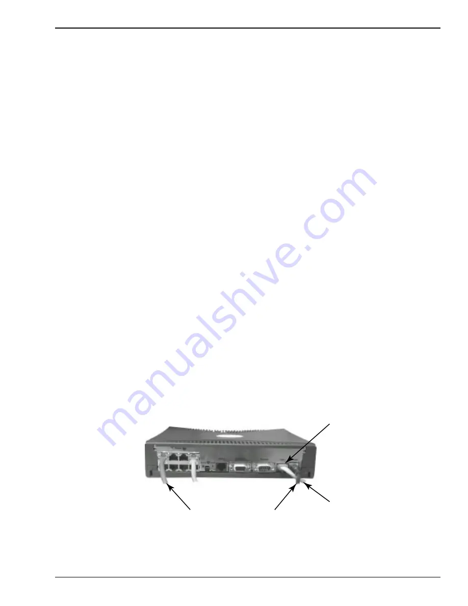
Connections
Connect a single phone line cable from the router port labeled “Line 1” (see Figure 6-2) to the designated
phone jack. If the provided cable is not long enough, you can purchase a longer one or make your own
(see “Standard Phone Cable Pin Out and Sources”). Next, connect the 9-pin AC power adapter to the
back of the router labeled “Power”. Connect the other end to any standard wall plug or extension cord.
Step 4:
Power on the Router
On the front of the router, press the Power button all the way in until it catches and remains depressed.
Different green and red lights will flash on the router, but should settle to 2 green lights with the labels
“WAN1: Ready” and “WAN 2: Channel 1”. Assuming the line is good, the router should automatically
be connected to the Internet.
Step 5:
Leave the Router On
Once the inside line and router are installed in the location, Ecast can test the line remotely and make sure
the line is good. If there are any problems, Ecast will work with the Operator and the Internet provider
to produce a swift solution. If the line is working properly, the Operator will be informed and the venue
will be ready for unit installation.
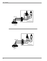
DSL LINE
POWER CORD
ETHERNET CABLE
FROM JUKEBOX
LINE 1
FIGURE 6-2
Содержание StarLink DLW-1
Страница 8: ......
Страница 22: ...DLW 1Phonograph 1 12 21822662 This page left intentionally blank...
Страница 37: ...Section 3 Venue Installation 21822662 3 11 THIS PAGE INTENTIONALLY LEFT BLANK...
Страница 39: ...Section 3 Venue Installation 21822662 3 13 THIS PAGE INTENTIONALLY LEFT BLANK...
Страница 50: ...DLW 1Phonograph 4 4 21822662 This page intentionally left blank...
Страница 72: ...DLW 1 Phonograph 5 22 21822662 This page intentionally left blank...
Страница 90: ...DLW 1Phonograph 8 8 21822662 This page intentionally left blank...
Страница 96: ...DLW 1 Phonograph 9 6 This Page Intentionally Left Blank...
Страница 120: ...DLW 1 Phonograph 10 24 21822662 SPANISHUSERINTERFACE...
Страница 128: ...DLW 1 Phonograph 10 32 21822662 This page left intentionally blank...
Страница 130: ...11 2 21822662 This page intentionally left blank...
Страница 132: ...11 4 21822662 Figure 11 1 Main Door Assembly External View 7 FLAT SCREEN Internet Jukebox 1 2 3 4 5 Starlink Starlink 6...
Страница 139: ...11 11 21822662 This page intentionally left blank...
Страница 141: ...11 13 21822662 7 8 Figure 11 3A Shell Assembly Internal View 1000 Watt 2 Channel Preamp...
Страница 145: ...11 17 21822662 This page intentionally left blank...


