9
x
Service and maintenance
FA ROTEX A1 BGe - 02/2014
45
Ɣ
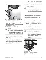
Remove the holding clamps on both upper heat insulation
layers (see fig. 9-3).
Ɣ
Remove both upper heat insulation layers.
Cleaning the silencer hood and boiler cladding
Ɣ
The low-maintenance plastic only needs to be cleaned with a
soft cloth and a mild detergent.
Ɣ
Do not use any cleaners with aggressive solvents (damage to
the plastic surface may occur).
9.2.2 Checking the connections and pipes
Ɣ
Check all gas and water lines and connections for leaks and
damage. If damaged, determine the cause and replace the
damaged parts.
Ɣ
Check system pressure.
If pressure is too low:
Ɣ
Detect and remedy the cause of the pressure loss.
Ɣ
Top up the system in accordance with chapter 4.10.
Ɣ
Check all components of the flue system for leakage and
damage. Repair damaged parts or replace them.
Ɣ
Check all electrical components, connections and pipes.
Repair damaged parts.
9.2.3 Checking and cleaning the condensate drain.
The connection and leakage line of the condensate drain must be
free from impurities.
Check the function of the condensate drain
1. Open the combustion chamber and lift up the combustion
chamber insert (see section 9.2.5).
2. Check the combustion chamber and clean if needed
(see section 9.2.5).
3. Check condensate drain for free flow and leaks:
Ɣ
Use a hose or bucket to fill a larger amount of water (about
5 l) into the lower combustion chamber and watch it drain.
Î
The water must flow quickly without puddling. If the water
doesn't drain quickly, the condensate box must be
cleaned and the drain connector checked (see "Dismount-
ing and cleaning the condensate box").
Ɣ
Check the connection and drain section for leakage.
Î
During drainage, water must not escape from the conden-
sate drain at any point. Fix any leaks.
Dismounting and cleaning the condensate box
1. Open the fixing belt (fig. 9-4, item 3).
Fig. 9-3
Remove the holding clamps on the heat insulation layers
WARNING!
Improperly performed work on live components can
endanger life and health of persons and hinder the op-
eration of the ROTEX A1.
Ɣ
Rectification of damage to live components on the
ROTEX A1 may only be carried out by authorised
and recognised heating experts.
RISK OF POISONING!
Escaping gases can cause breathing problems and
poisoning.
Ɣ
The condensate treatment unit must always be
connected and filled up when the boiler is
operating, otherwise flue gases could escape into
the installation room.
DANGER OF CHEMICAL BURNS!
The condensate box contains acidic condensate that
can lead to injury upon contact with the skin or eyes.
Ɣ
Wear protective clothing (safety glasses, rubber
gloves) when working on the condensate box.
Ɣ
If your skin comes in contact with anything, wash
the affected area immediately with tap water.
Ɣ
If the chemicals come in contact with eyes,
immediately wash with tap water and consult an
ophthalmologist.
1
Condensate box
2
Condensate plug connector on flue gas elbow
3
Fixing belt with snap closing
4
Flexible connecting hose
Fig. 9-4
Connections to the condensate box
Содержание A1 BG Inline
Страница 30: ...30 FA ROTEX A1 BGe 02 2014 6 x Control unit Fig 6 16 Wiring diagram ROTEX A1 BG for legend see tab 6 1...
Страница 60: ...60 FA ROTEX A1 BGe 02 2014 14 x Notes 14 Notes...
Страница 61: ...14 x Notes FA ROTEX A1 BGe 02 2014 61...
Страница 62: ...62 FA ROTEX A1 BGe 02 2014 14 x Notes...
Страница 63: ...14 x Notes FA ROTEX A1 BGe 02 2014 63...

