14
FA ROTEX A1 BGe - 02/2014
4
x
Set-up and installation
Surface temperature, minimum distance
– When operating independently of the ambient air with nomi-
nal output, the design does not allow temperatures >70°C on
any component outside the unit panels. Therefore, no mini-
mum distance is required to components made with flamma-
ble materials.
– A minimum distance of 50 mm between the flue gas duct and
flammable components should be maintained in a partial
room air-independent and ambient air-dependent mode (sep-
arate flue gas/air intake line).
– Do not store or use easily inflammable and easily combustible
substances directly next to the ROTEX A1.
4.4.2 Setting up the unit
Precondition
– The installation site complies with the respective country-spe-
cific regulations, as well as the minimum requirements
described in section 4.4.1.
Set-up
Ɣ
Remove the packaging and dispose of it in an environmen-
tally sound manner.
Ɣ
Install ROTEX A1 at the place of installation. Do not lift or
move the unit holding the panels.
Ɣ
Position the ROTEX A1 so that it can be hinged open without
any restriction.
Observe the connecting point for the gas supply, line routing
of the heating lines and the flue gas line.
Ɣ
Check for the horizontal level and correct installation height of
the ROTEX A1. You can adjust the height with the four height-
adjustable feet.
4.5 Air/flue system (LAS)
4.5.1 General instructions for flue system
Minimum requirements
For the design and dimensioning of the flue gas system, observe
all valid national combustion ordinances and country-specific
regulations.
Basically, for the flue gas system, you can use each flue gas pipe
according to EN 14471 with EU label, which meets the following
minimum requirements:
– Suitable for gas.
– Suitable for flue gas temperatures of at least 120 °C (temper-
ature class T120 or higher).
– Suitable for at least 200 Pa overpressure (pressure class P1
or H1).
– Humidity-resistant (condensation resistance class W).
– Sufficiently corrosion-resistant (corrosion resistance class 1
or 2).
The features of the flue system must be recognisable on the in-
stalled system.
Ɣ
Place the nameplate of the flue system in the installation
room.
Type of connections
– Straight, directly towards rear:
SET C,
15 50 79.03
.
– Height offset, towards rear:
SET D,
15 50 79.04
.
– Direct roof penetration:
SET F,
15 50 79.06
.
For other details and connection dimensions for the three ver-
sions of the flue gas pipe, see section 4.5.3.
– Each flue gas line must be installed with a suitable test
adapter for checking and setting the combustion values. The
ROTEX LAS construction sets each include a test adapter
(
D8 PA
,
15 50 79.00 93
).
Installation position and line height
– The maximum permitted flue gas counter pressure is
200 Pa
.
The pressure loss in the supply line must not exceed
50 Pa
.
– Angle of entry of the flue gas pipe into the chimney or instal-
lation shaft:
3°
.
– Slope for horizontal parts of the flue gas pipe:
3°
.
Counter-slopes are not allowed at any point in the flue gas
pipe.
– If the flue gas pipe needs more than 3 deflections >45°, then
the maximum permitted height for the flue gas pipe is reduced
by at least
1 m per deflection
(flue gas calculations may be
needed).
– If the horizontal connecting piece is extended, the maximum
permitted height of the flue gas pipe is reduced by exactly that
length.
– Flexible flue gas lines must not be used in horizontal connec-
tion sections.
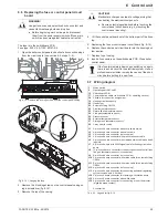
WARNING!
The storage tank plastic wall on the ROTEX A1 can
melt under the effects of external heat (>80 °C) and, in
the extreme case, can catch fire.
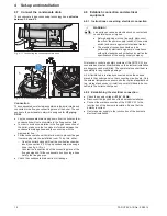
Ɣ
The ROTEX A1 can only be set up at a minimum
distance of 1 m from other sources of heat (>80 °C,
e.g. electric heaters, gas heaters, chimneys).
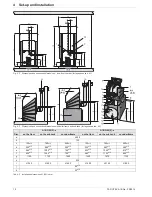
Fig. 4-5
Minimum distance for the installation of the A1 BG (for legend
see tab. 4-2)
A flue gas temperature sensor connected to the
ROTEX A1 controller effects a safety shutdown if the
flue gas temperature is too high.
WARNING!
There will be a
risk of poisoning
caused by flue gas
escaping within enclosed rooms that are inadequately
ventilated.
Ɣ
Install only approved flue gas systems.
Ɣ
The stipulated ventilation and rear ventilation must
be ensured, depending on the set up variant.
We recommend using the associated ROTEX flue gas
kits. They satisfy all requirements and are also fitted
with special acid-proof seals.
Содержание A1 BG Inline
Страница 30: ...30 FA ROTEX A1 BGe 02 2014 6 x Control unit Fig 6 16 Wiring diagram ROTEX A1 BG for legend see tab 6 1...
Страница 60: ...60 FA ROTEX A1 BGe 02 2014 14 x Notes 14 Notes...
Страница 61: ...14 x Notes FA ROTEX A1 BGe 02 2014 61...
Страница 62: ...62 FA ROTEX A1 BGe 02 2014 14 x Notes...
Страница 63: ...14 x Notes FA ROTEX A1 BGe 02 2014 63...

