7
x
Gas burner
FA ROTEX A1 BGe - 02/2014
37
Changeover from natural gas to liquid gas
1. Switch off the ROTEX A1 and secure against restart.
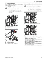
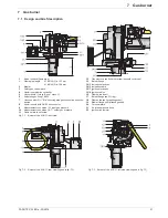
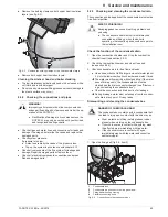
2. Remove the plug from the gas regulation block (fig. 7-6,
step 1).
3. Disconnect the air intake pressure hose (fig. 7-3, item 21)
from the safety gas control block (fig. 7-2, item 3).
4. Unscrew the Venturi nozzle with the safety gas control block
from the burner blower (fig. 7-6, step 2) and remove it
(fig. 7-7).
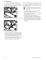
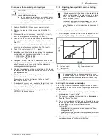
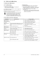
5. Unscrew and remove the 3 bolts that bolt down the venturi
nozzle to the safety gas control block (fig. 7-8, step 1).
6. Take of the venturi nozzle (fig. 7-8, step 2).
7. Insert the brass bezel for liquid gas between the safety gas
control block and the Venturi nozzle (fig. 7-8, step 3).
– A1 BG 25-e:
E15 00 605
– A1 BG 40-e:
E15 00 606
8. Using the 3 screws, screw the Venturi nozzle back on the
safety gas control block and then onto the burner fan. Special
attention must be paid to ensuring that the cork seal is
undamaged and correctly seated.
9. Replace the cable plug of the automatic firing unit to the gas
regulation block and place the air suction hose onto the safety
gas regulation block.
10. Start the burner check for leakage and adjust
(see section 7.3.2).
If necessary, adjust the performance limits (see tab. 7-2,
tab. 7-3 and section 7.3.5).
11. A gas type changeover and the adjusted thermal load must
be entered on the settings type plate and in the operating
manual and confirmed with signature.
12. Apply the equipment sticker for liquid gas (obtainable from
ROTEX) to the burner housing.
7.3.5 Adjusting the output limits and the starting
output
A targeted output adjustment is carried out by:
– Determining the matching setting values for the desired out-
put, from fig. 12-4 to fig. 12-7 or tab. 7-2 and tab. 7-3.
Limiting the maximum burner output
The limiting of the maximum burner output would be advisable,
for example, in the event of better sourcing charges for lower in-
stalled outputs.
1. Enter the access code for the heating expert and call up the
parameter level "Expert Config".
2. The maximum equipment output is limited by the parameter
"Fan Max". Enter "Fan Max".
3. The maximum output can still be set in a differentiated way for
the heating mode and hot water generation with reference to
these settings. Call up parameter level "System
Configuration".
– Enter the limit for the heating mode (parameter "Max-
Modgrad Heating").
– Enter the limit for the hot water charging mode (parameter
"MaxModgrad DHW").
4. Enter the output change on the settings type plate and in the
operating manual and confirm with signature.
WARNING!
Live parts can cause an electric shock on contact and
cause fatal burns or injuries.
Ɣ
Before beginning maintenance work, disconnect
the ROTEX A1 from the power supply (switch off
fuse, main switch) and secure against uninten-
tional restart.
The burner output is limited by entering parameter data
into the control system. The output values are entered
in the level "Expert Config" relative to the absolutel
maximum speed (100%).
Additional information for the parameter entry can be
found in the "ROTEX Control RoCon BF" documen-
tation. This documentation is included in the scope of
delivery.
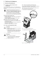
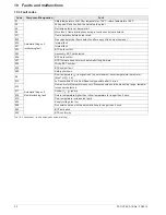
1
Maximum output
2
Minimum output
3
Starting output
Q
Burner load
Q
i
Relative burner load
Fig. 7-9
Procedure for determining the output settings
The values stated in the diagrams and tables have
been determined on the test bench. Deviations due to
the individual position and installation situation may
occur.
Содержание A1 BG Inline
Страница 30: ...30 FA ROTEX A1 BGe 02 2014 6 x Control unit Fig 6 16 Wiring diagram ROTEX A1 BG for legend see tab 6 1...
Страница 60: ...60 FA ROTEX A1 BGe 02 2014 14 x Notes 14 Notes...
Страница 61: ...14 x Notes FA ROTEX A1 BGe 02 2014 61...
Страница 62: ...62 FA ROTEX A1 BGe 02 2014 14 x Notes...
Страница 63: ...14 x Notes FA ROTEX A1 BGe 02 2014 63...

