46
FA ROTEX A1 BGe - 02/2014
9
x
Service and maintenance
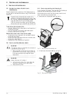
2. Lift the stabilising plate (fig. 9-5, item 2) and pull out the
connecting muff (fig. 9-5, item 1) from the condensate drain.
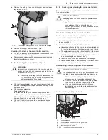
3. Lift the condensate box and empty it through the connection
hose (fig. 9-6).
4. Place collector container under the hose connection. Remove
the flexible connector hose from the condensate box
(fig. 9-7).
5. Pull the condensate box forwards under the boiler.
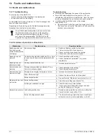
6. Cleaning the condensate box.
Ɣ
Rinse condensate box with flowing water against the flow
until clear water emerges (fig. 9-8). The condensate box
must be shaken in order to dislodge the deposits.
7. Check the flexible connector hose and drain connector and
clean if necessary.
8. Push condensate box under the boiler.
9. Plug flexible connector hose onto the condensate box
(see fig. 4-11).
10. Place the connection sleeve (fig. 9-5, item 1) firmly on the
condensate plug connection at the flue gas elbow.
11. Rotate the stabilising plate downwards and snap into place.
12. Close and tighten fixing belt (see fig. 9-4, item 3). Tighten the
belt so much that the wrapped connection cannot loosen itself
(insert a wedge if necessary).
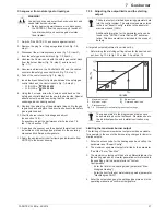
13. Fill condensate box with water (see chapter 4.7 "Connect the
condensate drain").
1
Connector sleeve for condensate connector
2
Stabilising plate
Fig. 9-5
Condensate box (plug connector)
Fig. 9-6
Emptying the condensate box
Fig. 9-7
Pull out connecting flexible hose
Fig. 9-8
Rinse condensate box
Fig. 9-9
Snap stabilising plate into place
Содержание A1 BG Inline
Страница 30: ...30 FA ROTEX A1 BGe 02 2014 6 x Control unit Fig 6 16 Wiring diagram ROTEX A1 BG for legend see tab 6 1...
Страница 60: ...60 FA ROTEX A1 BGe 02 2014 14 x Notes 14 Notes...
Страница 61: ...14 x Notes FA ROTEX A1 BGe 02 2014 61...
Страница 62: ...62 FA ROTEX A1 BGe 02 2014 14 x Notes...
Страница 63: ...14 x Notes FA ROTEX A1 BGe 02 2014 63...


