background image

6

7

6

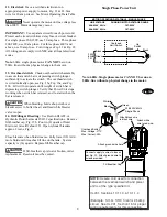
Latch Control Plate

1/4"-20NC x 1-3/4"

HHCS & Nylon Locknut

Clevis Pin & 

Retaining Rings

Locking Latch

Air Cylinder

Clevis

Air Cylinder

Bracket

Lowering Switch

Union Tee

To Left Column

Air Cylinder

To Main

Air Supply

1/4" Male

Connector

Fig. 13

(2) 5/16" x 3/8" Lg.

Pan Head Screw &

5/16" Ext. Tooth

Lockwashers

11.  Locking Latch & Air Cylinders:

A)

  To install cylinder, first slip dampening spacer over 

rod with rod in retracted position as shown below, Fig. 12.

B)

  Put locknut on threaded shaft and run it down to the 

dampening spacer.

C)

  Let rod extend and thread locknut down 1-1/2 more 

turns.

D)

  Screw Bracket Clevis onto shaft, position, and tighten 

locknut securely, Fig. 12.

E)

  Slide latch control plate into top cylinder Bracket 

Clevis.  

F)

  Insert Pivot Pin through hole in bracket and Latch 

Plate.  Install one clip ring on each side of Upper Pin.

G)

  Extend cylinder where column Pivot Bracket is to be 

mounted.

H)

  Slide one side of lower Pivot Pin (pre-installed & 

fixed in cylinder) into one half of the column Pivot Brack-

et.  Install Pivot Bracket into column using (2) 1/4"-20NC 

x 3/8" lg. PHMS, Fig. 12.

I)

  Install other half of Pivot Bracket the same way.

J)

  Install air lines from main air supply (with filter) to 

lowering valve.  Install air line from lowering valve to 

union tee then to the right column air cylinder.

K)

  Install air line from union tee to left column air cylin-

der. Fig. 14.

L)

  Mount lowering valve and bracket to column using 

(2) 5/16"-18NC x 3/8" lg. PHMS, Fig. 12.

Note

 Absence of air filter will void the warranty

 on all pneumatic components

Fig. 12

Locking Latch Engagement Test:

A)

  Raise carriages past the first latch position and 

then lower onto latches.

B)

  Check that the latches have fully engaged 

when the release switch is not depressed.

C)

  Raise carriages fully off latches.  Now depress 

release switch and check that the latches have 

fully disengaged.

D)

  Check for air leaks, make necessary adjust-

ments or repairs if required.

E)

  Install latch covers with 5/16"-18NC x 3/8" 

lg. BHCS, Fig. 13.

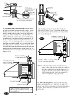
Note:  

Cut provided tubing with sharp blade to length 

as required.  Tubing must be cut square with no burrs.  

To assemble air line tubing into fitting, use firm, manual 

pressure to push tubing into fitting until it  

bot-

toms, see below.  If removal of the air line tubing from 

the fitting is ever required, hold Push Sleeve in (against 

fitting) and at the same time, pull out on tubing.

Fig. 14

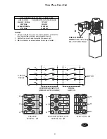
Fig. 12b

5/16-18NC x 3/8" lg. BHCS

Latch Control
Cover

Air Line
Tubing

Push
Sleeve

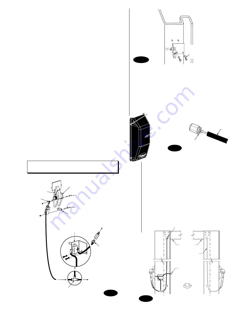
* Do Not Route Switch Cord Thru This Hole

Overhead

Assy.

Air line comes out

on the front side of 

lift on Left column

This line to

Main Air Supply

APPROACH

Rear View of Lift

Содержание Sprinter SPO15

Страница 1: ...ft All rights reserved IN20379 CO6363 1 Rev A 11 22 2005 I N S T A L L A T I O N I N S T R U C T I O N S SPO15 SPO18 Sprinter SPO15 3A0 Lifts Capacity 11 000 lbs Standard SPO15 300 Series Lifts Capaci...

Страница 2: ...n using the standard supplied 3 4 x 5 1 2 lg anchors if the top of the anchor exceeds 2 1 4 above the oor grade you DO NOT have enough embedment Fig 1 Drill 18 3 4 dia holes in concrete oor using hole...

Страница 3: ...IEW FROM APPROACH SIDE All Star Washers are to be mounted on the Right side column to ensure grounding of overhead limit switch Star Washers are not needed when mounting to Left Side column Notice the...

Страница 4: ...power unit bracket using Push Nuts to hold in place Fig 8a Mount unit with motor up to column bracket and install 4 5 16 star washers and 5 16 Nuts Install and hand tighten Branch Tee to pump until O...

Страница 5: ...easier to tie off lower studs rst A Run cable stud up through the lower tie off plate and or bracket s and or spacer s depending on the lift model Fig 11 B Push cable up until stud is above top of car...

Страница 6: ...1 spacer provided For 15 height carriages use pattern four with 472 cable Has 1 spacer provided For 16 6 height with 472 long cable or for 14 6 height with 424 long cable both use pattern one 4 3 1 2...

Страница 7: ...e Install air line from lowering valve to union tee then to the right column air cylinder K Install air line from union tee to left column air cylin der Fig 14 L Mount lowering valve and bracket to co...

Страница 8: ...er valve is open 14 Oil Filling Bleeding Use Dexron III ATF or Hydraulic Fluid that meets ISO 32 speci cations Remove ll breather cap Fig 15b Pour in 8 quarts of uid Start unit raise lift about 2 ft O...

Страница 9: ...TABLE THREE PHASE LINE VOLTAGE RUNNING MOTOR VOLTAGE RANGE 208 240V 50 60Hz 197 253V 400V 50Hz 360 440V 440 480V 50 60Hz 396V 528V 575V 60Hz 518V 632V FOR 3 POWER UNITS Attach Box using M5 x 10 PHMS...

Страница 10: ...in Fig 18 so that the rounded edge top side of the gear teeth is fac ing upward Then install the three 3 3 8 16NC x 1 1 2 Lg HHCS 12 total for all 4 arms and 3 8 Spring Lockwashers into the gear and a...

Страница 11: ...l if required Repeat air bleeding of cylinders 19 Final Adjustments Raise lift to check equalizer cable tension Below carriage grasp adjacent cables between thumb and fore nger with about 15 lbs effor...

Страница 12: ...erved Unless otherwise indicated ROTARY DOVER and all other trademarks are property of Dover Corporation and its affiliates Rotary World Headquarters 2700 Lanier Drive Madison IN 47250 USA www rotaryl...

Отзывы: