4
5
4
1
2
3
4
5
7
FRONT
6
7
5
5
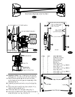
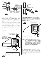
Hose runs down
approach side to
cylinder on left column.
Cylinder Bleeders
Hose runs through holes in
extensions, then through
holes in overhead.
1st Cable
2nd Cable
Upper Sheaves
Lower Sheaves
Fig. 10
ITEM
QTY.
DESCRIPTION
1
2
Hydraulic Cylinder
2
1
Power Unit Hose
3
1
Overhead Hose
4
1
Branch Tee
5
3
Hose Clips(5/8")
5
3
5/16"-18NC x 3/8” lg. PHMS
6
1
Hose Clips(1/2")
6
1
5/16"-18NC x 3/8” lg. PHMS
7
2
Hose Clips(5/8")
7
2
5/16"-18NC x 1/2” lg. PHMS
7
2
5/16"-18NC Nut
Fig. 9
10. Equalizer Cables:
Fig. 10 describes general cable
arrangements. It is easier to tie-off lower studs first.
A)
Run cable stud up through the lower tie-off plate,
and/or bracket(s), and/or spacer(s) depending on the
lift model, Fig. 11.
B)
Push cable up until stud is above top of carriage Fig.
11.
C)
Run nylon insert locknut onto studs so that 1/2" ex-
tends out from locknut Fig. 11.
D)
Pull cables back down through carriage Fig. 11.
E)
Run cable overhead and tie-off top studs and torque to
about 100 in-lbs., see Fig. 10 & Fig. 11.
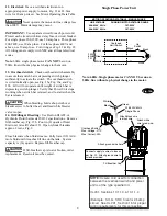
CAPACITY
15,000 LBS.
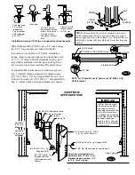
Use (4) 5/16”-18NC x 1-1/2” HHCS And Nuts
Push nuts hold bolts to brackets
On one bolt place
(2) 5/16” Star Washers
Fill Breather Cap
Overhead Hose
Crimped Hose
Sleeve (Typical)
Branch Tee
Power Unit (Short) Hose
For SPO15
CAPACITY
18,000 LBS.
For SPO18
Hose Routes Diagonally Across Overhead
Fig. 7b
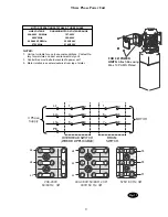
Fig. 8a
Fig. 8b

