44
6.
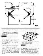
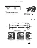
Mount switch assembly towards power unit column
as shown, Fig. 4, using (2) 1/4"-20NC x 3/4" lg. HHCS,
nuts and Star Washers.
For single phase lifts:
Insert 1/4"-20NC x 2-3/4" HHCS
through pivot hole in end of switch bar. Insert opposite
end of bar through slot in switch mounting bracket. Then
secure HHCS and Switch Bar to overhead as shown,
Fig. 6a, using (2) 3/4" spacers and 1/4”-20NC Locknut.
Tighten Hex bolt leaving 1/16” gap between the spacer
and the overhead assembly.
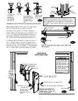
For three phase lifts:
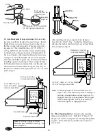
Remove Limit Switch cover, Fig.
6b. Insert Actuator end of Switch Bar into slot located
inside Limit Switch, Fig. 6c. A small amount of silicone
sealant on the lower part of the actuator will help hold it
in place. Insert 1/4"-20NC x 2-3/4" HHCS through pivot
hole in end of Switch Bar. NOTE which hole to use, Fig.
12. Then secure HHCS and Switch Bar to overhead as
shown, using (2) 3/4" spacers and 1/4”-20NC Locknut.
Tighten Hex bolt leaving 1/16” gap between the spacer
and the overhead assembly, Fig. 4. Replace limit switch
cover.
7.
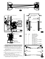
Install overhead assembly to column extensions
with (16) 3/8"-16NC x 3/4" lg. Flanged HHCS, Flanged
Locknuts and Star Washer, Fig. 7a. To ease installation,
use the tabs on the overhead to rest it on the extensions
when installing.
Fig. 6a
Install Rubber Grommet
On Non Approach Side
of Power Unit Column
and on Approach Side
of Other Column.
Attach overhead to extension using 3/8"-16NC x 3/4"
Flanged HHCS and 3/8"-16NC Flanged Locknuts.
Use (1) 3/8" Star Lockwasher on Power Unit Side.
8. Power Unit:
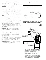
First install (1) star washer onto one
of the (4) 5/16"-18NC x 1-1/2" HHCS.
This is very
important for grounding.
Put the (4) 5/16"-18NC x 1-1/2"
HHCS thru holes in power unit bracket using Push-Nuts to
hold in place, Fig. 8a. Mount unit with motor up to column
bracket and install (4) 5/16” star washers and 5/16” Nuts.
Install and hand tighten Branch Tee to pump until O-ring
is seated. Continue to tighten the locknut to 10-15 ft-lbs.,
or until the nut and washer bottom out against the pump
manifold.
NOTE:
You may still be able to rotate the
Branch Tee. This is acceptable unless there is seepage at
the O-ring. If so, slightly tighten the locknut.
CAUTION
Over tightening locknut may tear O-ring or
distort threads in pump manifold outlet.
9. Hoses:
Clean adapters and hose. Inspect all threads
for damage and hose ends to be sure they are crimped, Fig.
8b.
Flared Fittings Tightening Procedure
1.
Screw the fittings together finger tight. Then, using
the proper size wrench, rotate the fitting 2-1/2 hex flats
(1/3 of a revolution).
2.
Back the fitting off one full turn.
3.
Again tighten the fittings finger tight; then using a
wrench, rotate the fitting 2-1/2 hex flats (1/3 revolution).
This will complete the tightening procedure and develop a
pressure tight seal.
Adapter & Hose Installation
1.
Install Pc. (2) with hose clamps, on power unit column
side connecting it to the cylinder (1) first.
2.
Install Pc. (3) with hose clamps starting at left
column cylinder (5) and working toward the right column.
All excess hose should be at bends & inside overhead
assembly.
3.
Install Pc. (4) into power unit.
4.
Connect Pc. (2) & Pc. (3) to Tee (4).
NOTE:
Route Power Unit hose inside columns using
slots provided at column base, Fig. 9. Route Overhead
Hose in column channel on outside of column, Fig. 9, Fig.
14. Overhead hose goes through holes beside sheaves in
the overhead weldment, Fig. 7b, Fig. 9.
Fig. 6c
Fig. 7a
Fig. 6b
Place Actuator Here.
A Small Amount Of Silicone Sealant
On The Lower Part Of The Actuator
Will Help Hold It In Place.
Cradle Bar
On Actuator
Actuator
Remove Screws
And Cover

