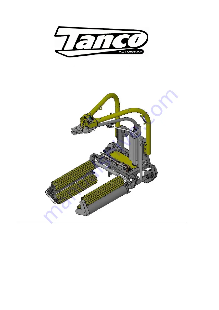
Tanco 1510 Скачать руководство пользователя страница 1


TANCO  AUTOWRAP 

1510 / 1514      

OPERATORS  HANDBOOK 

WD66-1510 / 1514-M0407 


Tanco Autowrap Ltd. 

Royal Oak Road 

Bagenalstown 

Co. Carlow 

Ireland 


Tel.: +353 (0)5997 21336 
Fax: +353 (0)5997 21560 

E-Mail: [email protected] 

Internet: www.tanco.ie 

Содержание 1510

Страница 1: ...UTOWRAP 1510 1514 OPERATORS HANDBOOK WD66 1510 1514 M0407 Tanco Autowrap Ltd Royal Oak Road Bagenalstown Co Carlow Ireland Tel 353 0 5997 21336 Fax 353 0 5997 21560 E Mail info tanco ie Internet www t...

Страница 2: ...any part not manufactured or having written approval by the sellers have been fixed g Any second hand goods or parts thereof Any allegedly defective part or parts returned to the seller must be sent...

Страница 3: ...FITTING ROLL OF FILM 20 7 0 CONTROLLER MANUAL 21 26 8 0 SPEED SETTING OF THE WRAPPING ARM 27 9 0 ADJUSTING THE OVERLAP 27 10 0 OPERATION INSTRUCTION 28 30 11 0 SPECIAL INSTRUCTIONS FOR TWIN 31 12 0 PE...

Страница 4: ...as more features than any other bale wrapping machine available TANCO AUTOWRAP can pick up the bale wrap and stack them without the operator leaving the tractor cab This system is protected by patent...

Страница 5: ...r advice before you make the problem worse than it is See also chapter 19 0 conditions of warranty TANCO AUTOWRAP 1510 1514 1510 1514 TWIN Height in working position Width min max Length min max Weigh...

Страница 6: ...y but is by definition not an emergency stop because it does not interrupt the feed Nevertheless it has an equivalent function so we have decided to call it an EMERGENCY STOP in this book 2 2 BECOME F...

Страница 7: ...onnected See more about the emergency stop in chapter 5 0 2 SQUEEZE DANGER BETWEEN THE MAIN FRAME AND THE WRAPPING ARM As earlier explained we have a wrapping arm with a dispenser and a plastic roll O...

Страница 8: ...tart of the next wrapping process When the cutter arm moves down to lock the plastic there can occur a squeeze danger between the cutter arm and the cutter holder The cutter blade that perforates the...

Страница 9: ...the tractor good stability Connecting heavy working implements often has an overall negative effect on the tractor s driving and braking capacity 2 9 TRANSPORTING When transported on a public road the...

Страница 10: ...ng plate which secures the second wrapping arm in the working position Then swing the arm in towards the davit See fig 2 8 4 To reduce the transport width of the TWIN machines at the same time prevent...

Страница 11: ...d the bale should have 90 1 00 p plastic 6 layers and the same amount of overlap If thinner plastic is used more layers should be applied if it is very hot the plastic will be stretched further and mo...

Страница 12: ...hed when working implements are fitted and connected Carry out the fitting procedures slowly and carefully and use separate and approved lifting equipment to make the work easier See section 2 on safe...

Страница 13: ...es have emergency stop arms on each brace and are fitted in the same way as they are on standard machines 4 4 MOUNTING OF SUPPORT ROLLER Lastly the support roller under the machine has to be mounted W...

Страница 14: ...tractor so that the machine is level with the ground It is recommended to use a hydraulic top link as this makes it easy to adjust the angle of the machine During the wrapping process it is recommend...

Страница 15: ...consists of the emergency stop button a communication cable and a power cable The control unit should be attached to a suitable place in the tractor cab using the supplied suction cup The control unit...

Страница 16: ...dealer Generally all tractors have got some counter pressure in their hydraulic return systems Some tractors have more than others Hose with red cap shall be connected to pressure P and hose with blue...

Страница 17: ...pumping and you do not get the benefit of the efficiency of your load sensing pump Thus Tanco Autowrap strongly recommend that if you are running the machine on tractor with LS hydraulics you should f...

Страница 18: ...d figs 2 7 2 8 2 9 and 2 10 7 Make sure that the plug in contact from the control unit is connected to the socket on the machine 8 Start the tractor and try out the functions A bale is not required fo...

Страница 19: ...o the lever arm and this activates a small electrical switch via a sliding contact 14 fig 5 2 If the electrical circuit is broken the hydraulic oil flow is cut off and all functions stop immediately A...

Страница 20: ...penser 6 4 Release the locking catch and allow the rollers to lie against the roll of film Pull the film from the roll and tie it to the bale 6 5 HEIGHT ADJUSTMENT OF PRE STRETCHER I PLASTIC FILM The...

Страница 21: ...rating Functions and Display 2 OPERATION 2 1 Operation in Automatic mode 2 2 Operation in Manual mode 2 3 Manual options in Automatic mode 2 4 Operations in Manual mode 2 5 The Display Menu 2 6 Select...

Страница 22: ...switched OFF via this switch before attempting any adjustment or maintenance to the machine Please follow ALL other safety instructions given in the manufacturers Operator Handbook for this machine 1...

Страница 23: ...stop by pressing the red stop button as this will impose unnecessary strain on the machine 2 3 Manual options in Automatic mode With the controller in automatic mode the following manual functions are...

Страница 24: ...mmary of the display menu NOTE There are additional sequences selectable in the Operator Setup menu but not shown in the table These sequences are for wrapper models to which this manual does not appl...

Страница 25: ...ng is Store A To select a particular store navigate the display menu using the 4 way switch Press the up down arrow keys to select the store then press the ENTER key to confirm the selection 2 7 Reset...

Страница 26: ...reduction at the end of the wrapping cycle Delay to Stop 1 0s 0 9s 1300EH 1510S 1514 1510T 1514T Set to adjust the Stop position of the wrap arm Rotation After 0 0s All Set time period to rotate the b...

Страница 27: ...peed of tractor engine do not increase the wrapping speed it only increases the oil flow into the system and by that also the temperature in the hydraulic system Fast Speed Valve Valve No 6 Roller Spe...

Страница 28: ...osition on the wrap arm It is fastened with two bolts To ensure the plastic film is always hitting the middle of the bale you must adjust the roller arm stops see section 10 3 The film dispenser is de...

Страница 29: ...width between the rollers while wrapping This is most in common when wrapping bad shaped and loosely packed bales If the machine has problems rotating the bale you can move the rollers in or out with...

Страница 30: ...y the controller is reset and the bale counter is incremented 10 11 STORAGE PLACE At the storage place the bales should be placed systematically Start at the right hand side and stack to the left Lowe...

Страница 31: ...oned perpendicular to the machine i e the stop position Position the wrap arm correctly in Manual mode pressing and holing the wrap slow button Then fix both the film ends securely in the cutters See...

Страница 32: ...g at the base of the cylinder until the springs are almost completely compressed 12 4 PIVOT BEARINGS The link bearings between the main frame and roller arms must be greased once a week or as required...

Страница 33: ...s is fitted on a conical journal and can therefore fall off as soon as the fixing screw is removed from the end of the journey Always secure the wrapping arm with a strap or something similar to preve...

Страница 34: ...magnet valves and switches on the machine See fig 13 1 The electric cables to the valves and switches are numbered from 1 to 15 and extend to the listed appliances below 1 C S Open 2 C S Close 3 Roll...

Страница 35: ...d again before it stops when number of programmed revolutions is obtained See also chapter 7 11 The signals from the control unit are all the time sent to the magnet valves that shall be activated The...

Страница 36: ...valve blocks are marked with every individual valve number as is the hydraulic circuit During the wrapping sequence all three hydraulic motors on the machine are connected in series i e the oil goes...

Страница 37: ...y this valve remains open and the oil circulates constantly from and to the tractor As soon as one of the control box functions is selected this valve will close and simultaneously open the LC valve f...

Страница 38: ...ot have V numbers but have the same number as the electric cables to which they are connected See the diagram of connections fig 13 1 1 Cutter open 2 Cutter close 3 Roller width in 4 Roller width out...

Страница 39: ...h an orifice that limits the speed After about half a revolution the two stage valve opens and the oil flows outside this nozzle This makes the wrapping arm turn at full speed The same thing happens w...

Страница 40: ...or s outflow side when the arm stops The valve releases oil from the outflow side of the motor into the inflow side V18 Safety valve on the minus side This limits the maximum torque on the wrapping ar...

Страница 41: ...pressure drops the outputs switches again and the machine squeezes The cycle repeats until the bale is fully loaded V11 DOUBLE DRIVE Valve This rotates all the rollers during loading with the left and...

Страница 42: ...nd the motor will brake V14 Rotation stop valve standard Electric cable no 12 This valve will allow the rollers to stop rotating while the wrapping arm continues to turn This can be useful on the 1514...

Страница 43: ...RETURN PRESSURE The return pressure can be too high With high return pressure the machine s functions will get less power High return pressure means also that you need more power to operate the valve...

Страница 44: ...s fails the reason can be that dirt is stuck in the valve that prevents the spool sliding to open and or close Try to maneuver the function manually by pressing the point of a screwdriver into the end...

Страница 45: ...not receiving any power or there is dirt in the valve so that the slide valve is not closing See section 16 1 and 16 3 If the power is OK unscrew the valve and clean it or replace it If necessary ask...

Страница 46: ...y catch has not been released See section 4 12 The solenoid valve no 5 is not receiving power or there is dirt in the valve See section 16 1 and 16 2 Clean the valve or replace if defective The volume...

Страница 47: ...cutter cylinder is dropping The fault is probably in the pilot controlled check valve See section 14 2 Replace defective valve or have it tested by your dealer The fault could also be that the check...

Страница 48: ...Autowrap 1514 1510 Operator s manual There are 3 basics which must ALWAYS be followed if the machine is to function correctly Working Pressure 185 Bar 2600Psi Power Supply 12V Back Pressure Max 10 Ba...

Страница 49: ...49 Tanco Autowrap 1514 1510 Operator s manual 18 0 HYDRAULIC CHART AUTO WRAP 1510 1514 TWIN...

Страница 50: ...50 Tanco Autowrap 1514 1510 Operator s manual 19 0 Wiring Diagram...

Страница 51: ...OWING PRODUCT TANCO AUTOWRAP MODEL 1510 14 SERIAL NO To which this declaration relates corresponds to the essential requirements of the Directive 89 392 336 EEC as amended To conform to these essentia...

Отзывы: