Installation
AYC-B7661 Installation Manual
17
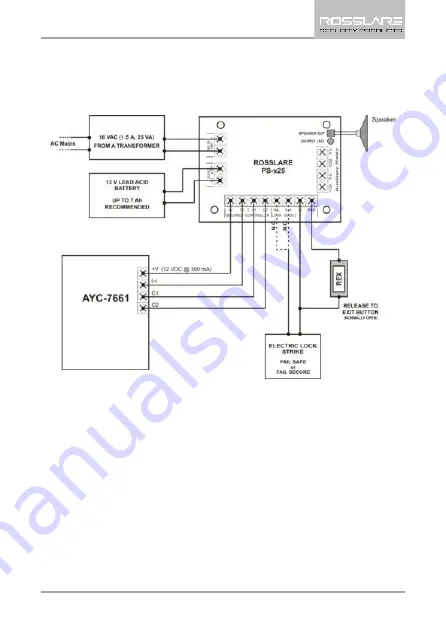
Figure 4 shows the wiring for the controller application using a dual-relay secure application appurtenance.
Figure 4: Controller Wiring – Using a Dual-Relay Secure Application
Appurtenance
Страница 1: ...AYC B7661 MIFARE Full Finger Capacitive Biometric Reader Controller Installation Manual ...
Страница 2: ...al property rights covering the subject matter in this manual TEXTS IMAGES AND ILLUSTRATIONS INCLUDING THEIR ARRANGEMENT IN THIS DOCUMENT ARE SUBJECT TO THE PROTECTION OF COPYRIGHT LAWS AND OTHER LEGAL RIGHTS WORLDWIDE THEIR USE REPRODUCTION AND TRANSMITTAL TO THIRD PARTIES WITHOUT EXPRESS WRITTEN PERMISSION MAY RESULT IN LEGAL PROCEEDINGS The furnishing of this manual to any party does not give t...
Страница 3: ... 3 2 2 Wiring the Unit as a Controller 15 4 Reader Controller Configuration 19 4 1 Configuring the Unit 19 4 2 Configuration Procedure 19 5 Fingerprint Enrollment 21 5 1 Enrollment in 1 N Mode 21 5 2 Enrollment in 1 1 Mode 23 5 3 Adding ID from a Card Reader 1 N Mode 25 6 Modes of Operation 26 6 1 Boot Mode 26 6 2 Configuration Mode 26 6 3 Standby Mode 26 6 4 Read Mode 27 6 4 1 Valid Card or Finge...
Страница 4: ...Table of Contents iv AYC B7661 Installation Manual 6 6 Factory Defaults 29 A User Spreadsheet 30 B Limited Warranty 32 ...
Страница 5: ...ntations 12 Figure 2 AYC B7661 Removing the Top Cover 13 Figure 3 Wiring Layout for Reader Configuration 14 Figure 4 Controller Wiring Using a Dual Relay Secure Application Appurtenance 17 Figure 5 Controller Wiring Using the Internal Power 18 Figure 6 Controller Wiring Using the External Power 18 ...
Страница 6: ...List of Tables vi AYC B7661 Installation Manual List of Tables Table 1 Wiring the Reader to the Controller 15 Table 2 Wiring the Unit as a Controller 16 ...
Страница 7: ...efore not all functions described in this manual may be available in the specific system and or product configuration you purchased Incorrect operation or installation or failure of the user to effectively maintain the system relieves the manufacturer and seller from all or any responsibility for consequent noncompliance damage or injury The text images and graphics contained in the manual are for...
Страница 8: ...nits AC 015 AC 115 AC 020 AC 215 AC 225 AC 425 AC 525 and ExpansE 1 1 Reader Features When using the AYC B7661as a reader it has the following features MIFARE card reading followed by fingerprint in 1 1 mode Rosslare s algorithm for ID code derived from the fingerprint template in 1 N mode Supports a back tamper sensor and a tamper output signal Supports a Lockout feature for increased security Co...
Страница 9: ...door is unlocked is configurable using the configuration card 1 to 99 seconds Bell feature is available with the PS x25 secured power supply Depends on the AUX input Programmable door lock timer Ability to enable or disable auxiliary input output and bell No PC is required for fingerprint enrollment unit uses cards to configure fingerprint templates REX input Lock output Aux input This is the brow...
Страница 10: ...ended Input Voltage 5 to 16 VDC Absolute Maximum non operating 18 VDC Maximum Input Current 1 1 Standby 60 mA 12 VDC Read 100 mA 12 VDC Maximum Input Current 1 N Standby 95 mA 12 VDC Read 100 mA 12 VDC Tamper Output Open collector active low Max sink current 32 mA Maximum Controller Cable Distance 150 m 500 ft using 18 AWG shielded cable Frequency 13 56 MHz Card Compatibility MIFARE ISO14443A 3 st...
Страница 11: ...n Manual 11 Environmental Characteristics Operating Temperature Range 25 C to 60 C 13 F to 140 F Operating Humidity Range 30 to 85 non condensing Physical Characteristics Dimensions H x W x D 100 x 54 x 42 mm 3 9 x 2 1 x 1 7 in Weight 156 g 5 5 oz ...
Страница 12: ...side To mount the unit 1 Determine an approximate surface location for the reader 2 Peel off the back of the self adhesive mounting label template and place it on the required mounting location 3 Using the template as a guide drill two holes of the size indicated on the template on the surface to mount the unit 4 Insert the wall plugs into both mounting holes 5 Drill a 10 mm 7 16 hole for the cabl...
Страница 13: ...er 7 Carefully remove the snap off front cover of the unit to reveal two screw holes 8 Insert the unit s cable wire into the cable hole and move the unit flush with the wall 9 Using the two mounting screws screw the unit to the wall through the two wall plugs 10 Route the cable from the unit to the Controller when configuring as a reader Section 3 2 1 PS x25 power supply when configuring as a cont...
Страница 14: ...ader If you connect the unit to a standard access control unit it automatically functions as a reader Figure 3 Wiring Layout for Reader Configuration The AYC B7661unit is connected with an 8 wire 46 cm 18 cable To connect the unit as a reader to a controller 1 Prepare the unit s cable by cutting the cable jacket back 3 2 cm 1 and strip the wire 1 3 cm 2 Prepare the controller cable by cutting the ...
Страница 15: ...st have a common ground A linear power supply is recommended Attach the cable shield wire on the reader to an earth ground best or to a signal ground connection at the panel or power supply end of the cable This configuration is best for shielding the reader cable from external interference 3 2 2 Wiring the Unit as a Controller If you connect the unit to a Rosslare PS x25 secured power supply it a...
Страница 16: ...PS x25 C 1 White Communication Wired to the PS x25 C 2 Green Communication Wired to the PS x25 AUX IN Brown Auxiliary Input Wired to input Attach the cable shield wire on the unit to an earth ground best You can also attach it to a signal ground connection at the panel or power supply end of the cable This configuration is best for shielding the controller cable from external interference 4 Trim a...
Страница 17: ...C B7661 Installation Manual 17 Figure 4 shows the wiring for the controller application using a dual relay secure application appurtenance Figure 4 Controller Wiring Using a Dual Relay Secure Application Appurtenance ...
Страница 18: ...Figure 5 shows the auxiliary output connection using the internal power Figure 5 Controller Wiring Using the Internal Power Figure 6 shows the auxiliary output connection using the external power Figure 6 Controller Wiring Using the External Power ...
Страница 19: ...o browse between 1 1 and 1 N modes The Master and Configuration cards are configured using the Desktop Programmer CP R26 Refer to the CP R26 Hardware and AS B01 Software Manual for more details 4 2 Configuration Procedure The reader does not work until it is configured upon initial use It is recommended to configure the reader one time only following installation and its initial use However if nee...
Страница 20: ...ly together If the configuration is not valid an error beep is generated If the reader is being configured for the first time the reader will not work until a successful configuration is performed If the reader is already in use then following a failed configuration the reader returns to Standby mode and continues to work with its previous configuration settings ...
Страница 21: ...Rosslare s CP R26 unit to generate these cards 5 1 Enrollment in 1 N Mode In 1 N mode the unit identifies users according to their fingerprints only Before enrolling users it is recommended to create a list of all users and their record number see Appendix A The unit accepts up to 107 users To enroll fingerprints 1 For first time use configure the reader as explained in Chapter 4 2 When the reader...
Страница 22: ...rt beeps and the LEDs blink green The user s fingerprint template is then stored in the defined record within the unit If an enrollment error occurs the unit emits an error tone and the LEDs turn red for about one second For people who cannot enroll their finger In Reader mode there is an option to use the reader with card only CSN or sector In Controller mode you can enroll a user card with the A...
Страница 23: ... 1 For first time use configure the reader as explained in Chapter 4 2 When the reader is in standby mode present the Enroll card to the unit Both LEDs flash orange 3 Present the record number 10 and 1 cards the number of times required to reach the desired record number Each time a card is presented the reader emits one beep For example to enroll a fingerprint to record number 32 present the 10 c...
Страница 24: ...ts one beep For example to enroll a fingerprint to record number 32 present the 10 card three times followed by the 1 card twice 3 Present the Delete card If valid the unit emits three short beeps and the LEDs blink green The users do not need to place their finger on the unit s sensor If an error occurs the unit emits an error tone and the LEDs turn red for about one second To add a user card to ...
Страница 25: ...d s ID to the template In this case the user s ID is sent to the controller instead of the previous ID To add an ID from a user card 1 Present the Add Card card Both LEDs flash orange 2 To get to the desired record number do one of the following Ask the users whose ID cards you wish to add to place the finger linked to each record number Present the record number 10 and 1 cards the number of times...
Страница 26: ...ree seconds during which the red LEDs flash simultaneously 6 2 Configuration Mode Refer to Section 4 2 on how set the reader to Configuration mode The Configuration card is configured using the Desktop Reader CP R26 and the Card programmer and Fingerprint enrollment Refer to the CP R26 Hardware and AS B01 Software Manual for more details 6 3 Standby Mode The reader enters Standby mode After the Bo...
Страница 27: ...reen indicating to users to place their finger on the unit s sensor In either mode for people who cannot enroll their finger there is an option to use the reader with card only CSN or sector 6 4 1 Valid Card or Fingerprint Read When card and or fingerprint reads are valid the following sequence occurs 6 4 1 1 In 1 N Mode 1 While the unit is in Standby mode users place their finger on the unit s se...
Страница 28: ...rd or Fingerprint Read An invalid card or fingerprint read can occur when There is an error in fingerprint presentation for example a user places the finger incorrectly There is a mismatch between the fingerprint and the template for example a user presents the wrong finger An invalid card read can occur when the card is not verified When a card or fingerprint read is invalid the following sequenc...
Страница 29: ...ockout mode when there are a number of invalid card and or finger reads within a 30 second period During Lockout mode the two LEDs flash red simultaneously for 1 minute After 1 minute the reader enters Standby mode The default number of invalid reads before the reader enters Lockout mode is 5 The number of invalid reads can be programmed to be 1 10 The default duration of Lockout mode is 1 minute ...
Страница 30: ...des of Operation 30 AYC B7661 Installation Manual A User Spreadsheet User User Name User User Name 1 55 2 56 3 57 4 58 5 59 6 60 7 61 8 62 9 63 10 64 11 65 12 66 13 67 14 68 15 69 16 70 17 71 18 72 19 73 ...
Страница 31: ...User Spreadsheet AYC B7661 Installation Manual 31 20 74 21 75 22 76 23 77 24 78 25 79 26 80 ...
Страница 32: ...ted Warranty The full ROSSLARE Limited Warranty Statement is available in the Quick Links section on the ROSSLARE website at www rosslaresecurity com Rosslare considers any use of this product as agreement to the Warranty Terms even if you do not review them ...
Страница 33: ... rosslaresecurity com Europe Rosslare Israel Ltd Rosh HaAyin Israel Tel 972 3 938 6838 Fax 972 3 938 6830 support eu rosslaresecurity com Latin America Rosslare Latin America Buenos Aires Argentina Tel 54 11 4001 3104 support la rosslaresecurity com China Rosslare Electronics Shenzhen Ltd Shenzhen China Tel 86 755 8610 6842 Fax 86 755 8610 6101 support cn rosslaresecurity com India Rosslare Electr...