Page 42
System configuration
© 2017 Ropam Elektronik
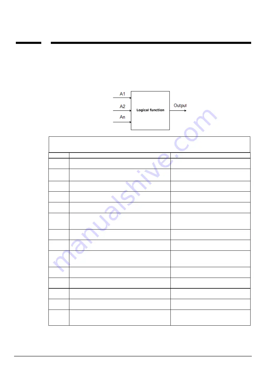
Logical functions.
The logical functions interpret used arguments and the logical condition,the result is written to the
output or to the marker.There are eight conditions, under one can be used 20 arguments, one logical
condition and the logical result entered into one output or marker.
Arguments
Symbol
Description
Logical values
I1
÷I8
input status, binary value 0 or 1,
object type Binary Input
0 = input not violated
1 = entry violated
O1÷O4
physical output state, takes a binary value 0 or 1,
object type Binary Output
0 = inactive output
1 = active output
M1÷M16
value markers, takes a binary value 0 or 1,
object of type Binary Value
0 = marker value 0
1 = marker value 1
L1÷L8
Total value counters, 8 independent
counters
-2 147 483 648
÷
2 147 483 647
tk1÷tk4
indicators of timer / calendar, takes a binary value
0 or 1
1 = timer on (ON-> OFF)
0 = timer off (OFF-> ON).
tla
Temperature indicator for threshold L, takes binary
value 0 or 1, object type Binary Value
1 = temp. < L
0 = temp > (L+histereza)
tha
Temperature display for threshold H, takes a
binary value 0 or 1, object type Binary Value
1 = temperature> H
0 = temp <(H-hysteresis)
ft
Temperature sensor failure indicator., assumes a
binary value 0 or 1
0 = no failure
1 = temperature sensor failure
tv
temperature value from sensor T1, measurement
interval every 30 seconds, value [° C], number
with sign
aia1÷aia2
A binary indicator of threshold A from analog input
AI (I7 or I8) [mV] or [mA]
binary state 0 or 1
aib1÷aib
2
binary indicator of threshold B from analog input AI
(I7 or I8) [mV] or [mA]
binary state 0 or 1
aiv
Analog input voltage value AI [mV] (I7, I8)
Range of values: 0-10000 [mV] or 4-20
[mA]
ac
failure rate of primary supply voltage (AC),
assumes a binary value 0 or 1
0 = basic voltage present
1 = basic voltage absent
bf
indicator of battery failure of emergency power
supply, status from the supervised power supply,
takes a binary value 0 or 1
0 = no failure
1 = battery failure
Содержание BasicGSM 2
Страница 8: ...Page 04 Introduction 2017 Ropam Elektronik BasicGSM 2 BasicGSM PS 2 BasicGSM D4M 2 BasicGSM D4M PS 2...
Страница 10: ...Page 06 System description 2017 Ropam Elektronik View BasicGSM 2...
Страница 43: ...Page 39 System configuration 2017 Ropam Elektronik Output setting Settings in the LogicProcessor tab...
Страница 53: ...Page 49 System configuration 2017 Ropam Elektronik DelayKeepOn TRG R O OneShot TRG R O TimeOffDelay TRG R O...
Страница 54: ...Page 50 System configuration 2017 Ropam Elektronik Blinker TRG R O MonoBi TRG R O Delay Alter TRG R O...
Страница 78: ...Page 74 System configuration 2017 Ropam Elektronik About the module...


