


Publication 1747-UM013B-EN-P - January 2005
Scanner Configuration and Programming
4-19
address will not force a reset. To remove the reset condition, reset the
bit (corresponding to the device logical starting address) to 0. See the
mode table on page 4-22.
Default:
The SLC processor resets all bits in this field to 0 when it
enters Run or Test mode.
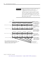
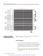
Example of Device Reset Control
The application has commanded the device starting at Logical Rack 0,
Group 0 (M0:e.16/0) to a reset condition (bit set to 1). The default
setting for all device reset bits is 0.
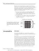
M0 File - Remote Output Reset Control
M0 Words 24 through 27 -
you use these words to command a
logical device to reset all of its outputs when the SLC processor leaves
the Run mode and enters the Test, Program, or Fault mode (regardless
of the device’s
Hold Last State
setting).
Resetting the bit (corresponding to the starting address of a device) to
0 allows the Hold Last State switch on the logical device to determine
output operation when the SLC processor leaves the Run mode.
M0 File
0
1
2
3
4
5
6
7
8
9
10
11
12
13
14
15
Bit Number (decimal)
M0 (Control) File W
ords 16 through 19
Logical Rack 0 Device Reset Word 16
M0:e.16
0
0
0
0
x
x
x
x
x
x
x
x
x
x
x
x
M0:e.17
0
0
0
0
x
x
x
x
x
x
x
x
x
x
x
x
M0:e.18
0
0
0
0
x
x
x
x
x
x
x
x
x
x
x
x
M0:e.19
Logical Rack 1 Device Reset Word 17
Logical Rack 2 Device Reset Word 18
Logical Rack 3 Device Reset Word 19
e = slot number of the SLC rack containing the scanner
x = bit not used/defined
0
0
0
0
x
x
x
x
x
x
x
x
x
x
x
x
Not Defined
Starting Group
0
2
4
6
0
0
0
0
x
x
x
x
x
x
x
x
x
x
x
x
0
0
0
0
x
x
x
x
x
x
x
x
x
x
x
x
0
0
0
0
x
x
x
x
x
x
x
x
x
x
x
x
1
0
0
0
x
x
x
x
x
x
x
x
x
x
x
x
0
1
2
3
4
5
6
7
8
9
10
11
12
13
14
15
M0 File
M0:e.16
M0:e.17
M0:e.18
M0:e.19
1
1
0
0
1
0
0
0
0
1
0
0
0
1
0
0
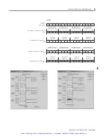
Device Address, Word 1
G File
M0 (Control) File
Bit Number (decimal)
e = slot number of the SLC rack containing the scanner
x = bit not used/defined
Logical Rack 0 Device Reset Word 16
Logical Rack 1 Device Reset Word 17
Logical Rack 2 Device Reset Word 18
Logical Rack 3 Device Reset Word 19
RIO Logical Rack 0
Starting Group
0
2
4
6
RIO Logical Rack 1
Starting Group
0
2
4
6
RIO Logical Rack 2
Starting Group
0
2
4
6
RIO Logical Rack 3
Starting Group
0
2
4
6
Artisan Technology Group - Quality Instrumentation ... Guaranteed | (888) 88-SOURCE | www.artisantg.com


