Publication 1747-UM013B-EN-P - January 2005
Scanner Configuration and Programming
4-5
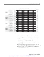
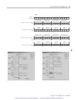
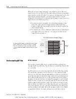
configuration. The G file consists of five words which are described
below.
Word 0 -
contains scanner information for the SLC processor. Your
programming device
automatically
sets up Word 0. Do not attempt to
alter word 0.
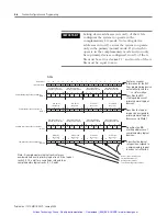
Word 1, Primary/Normal Logical Device Address -
specifies the
logical starting address of each primary/normal RIO link device. The
logical address consists of the logical rack number (0, 1, 2, or 3) and
starting logical group (0, 2, 4, or 6). Each bit in this word represents a
logical address. To specify an address you place a 1 at the bit
corresponding to the starting logical address of each logical device.
Word 2, Primary/Normal Device Logical Image Size -
specifies the
logical image size (amount of scanner I/O image) of the devices set in
word 1. As with word 1, these bits correspond to RIO logical rack and
logical group numbers. To specify image size, you place a 1 at each
group a device occupies.
Word 3, Complementary Logical Device Address -
specifies the
logical starting address of each complementary RIO link device. The
logical address consists of the logical rack number (8, 9, 10, or 11
because a complementary device is always 8 above its primary) and
starting logical group (0, 2, 4, or 6). Each bit in this word represents a
logical address. To specify an address you place a 1 at the bit
corresponding to the starting logical address of each logical device.
Word 4, Complementary Device Logical Image Size -
specifies the
logical image size (amount of scanner I/O image) of the
complementary devices set in word 3. As with word 3, these bits
correspond to RIO logical rack and logical group numbers. To specify
image size you place a 1 at each group a device occupies.
IMPORTANT
The term “primary” is used in conjunction with the
term “complementary,” when referring to a
complementary I/O configuration. “Primary” refers to
I/O image space found in Logical Racks 0 through 3
when in complementary I/O mode and “normal”
refers to the same image space (racks 0 through 3)
when not in complementary I/O mode.
Artisan Technology Group - Quality Instrumentation ... Guaranteed | (888) 88-SOURCE | www.artisantg.com


