


Publication 1747-UM013B-EN-P - January 2005
4-14
Scanner Configuration and Programming
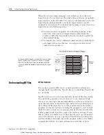
When the scanner image assigned to an adapter is more than one
logical device, the scanner sees the single physical device as multiple
logical devices on the RIO link. The scanner communicates with each
logical device independently, even if the logical devices are all
assigned to one adapter. If a physical device image is more than one
logical device, the following is true:
•
The scanner does not update all of the adapter image at the
same time. The number of logical devices determines the
number of RIO discrete transfers that are needed to update the
entire adapter image.
•
The adapter may receive different communication commands for
each logical device. In this case, the adapter decides which
command it responds to.
Understanding M Files
M Files Overview
The scanner provides RIO device control and status information
through the M0 and M1 files. The M0 file is a control file. The M1 file
is a status file
The SLC processor does not automatically update M file data during
the end of the program scan as it does I/O scans. Instead, M file
values act as interrupts and are immediately read from or written to
upon the execution of the ladder logic instruction in which they are
used. When M file data (bits or words) is addressed in the ladder
program, the processor stops scanning the program to read or write
the M file data to/from the scanner module. M file bits/words in the
ladder program will, therefore, impact the ladder scan time. If scan
time is critical, it is better to set binary file bits and copy them all at
once to the M0 file, or copy a portion of the M1 file to a binary file
and then address the binary file in the program. Refer to the ladder
example that follows. For more information on M files, refer to
Group 2
Group 3
Group 0
Group 1
Group 6
Group 4
Group 5
Group 7
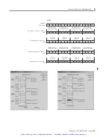
Logical
Rack 1
Group 7
Group 5
Group 6
Group 3
Group 4
Group 1
Group 2
Group 0
Logical
Rack 0
Adapter
Image
Logical
Device
Logical
Device
Bit Number (Decimal)
0
7
8
15
Scanner Input or Output Image
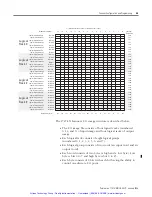
In this example the adapter is configured to start at Logical
Rack 0, Logical Group 0, and uses 14 words of I/O image.
Note that two RIO discrete transfers are required for the
scanner to update the adapter image containing two logical
devices.
Artisan Technology Group - Quality Instrumentation ... Guaranteed | (888) 88-SOURCE | www.artisantg.com


