Appendix
C
CE Conformity
CE Compliance
This drive is a component intended for implementation in machines or systems for
the industrial environment. It is CE marked for conformity to the Low Voltage (LV)
Directive 73/23/EEC when installed as described. It also has been tested to meet
the Council Directive 89/336 Electromagnetic Compatibility (EMC). The
standards used for this testing are, LV: EN50178, EN60204-1, EMC EN61800-3,
EN50081-1, EN50082-2. These tests were conducted with a PWM frequency
(Parameter 49) of 4.0 kHz.
Important:
The conformity of the drive and filter to any standard does not
guarantee that the entire installation will conform. Many other
factors can influence the total installation and only direct
measurements can verify total conformity. It is therefore the
responsibility of the machine manufacturer, to ensure, that the
conformity is met.
A copy of the Declaration of Conformity (DOC) is available from your local
Rockwell Automation Sales Office.
Essential Requirements for a Conforming EMC Installation
The following seven items are required for CE Conformance:
1. An input line filter module (see Appendix B,
Accessories and Dimensions
)
must be installed to reduce conducted emissions.
160-LF Filters
These units have been tested with a maximum motor cable length of 75 meters
(250 feet) for drives rated 200 – 240VAC, and 40 meters (133 feet) for drives
rated 380 – 460VAC.
160S-RF Filters
These units have been tested with a maximum motor cable length of 25 meters
(80 feet) for both 230V and 460V units.
2. The drive system must be mounted in a shielded enclosure to reduce radiated
emissions.
3. Grounding of equipment and cable shields must be solid, with low impedance
connections.
4. Motor and control cables entering the shielded enclosure must have EMC-
tested shielded cable clamps, or grounded metal conduit.
5. All motor cables must use shielded cable, or be in grounded metal conduit.
6. All control and signal wiring must use shielded cable or be in grounded metal
conduit.
7. The Common terminals (TB3-3
and
7) must have a solid connection to ground
terminal/protective earth.
Содержание Allen-Bradley 160 SSC Series
Страница 12: ...1 6 Getting Started End of Chapter ...
Страница 58: ...5 20 Parameters and Programming End of Chapter ...
Страница 66: ...A 4 Specifications End of Chapter ...
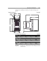
Страница 75: ...Accessories and Dimensions B 9 Drilling Template A Figure B 10 ...
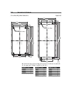
Страница 76: ...B 10 Accessories and Dimensions Drilling Template B Figure B 11 ...
Страница 82: ...C 6 CE Conformity End of Chapter ...
Страница 87: ......


