


RS-Helios-1610 User Manual
30
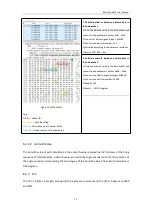
Figure A-2.2 Angle Pulse Setting Page of the LiDAR Web Interface
1.
Angle Pulse Setting:
Set the angle pulse triggering feature, which by default is turned off.
2.
Trigger Mode:
There are two starting angle trigger modes. Mode1 means that the starting
pulse width is increased by 25% (default), and Mode2 means that the starting pulse width is not
increased;
3.
Group Switch:
Turn on/off the "Pulse Trigger Switch", when "All On" is checked, all groups of
SYNC angle pulse trigger settings are activated for setting. The Group Switch is by default
checked "All Off";
4.
Group:
Referring to SYNC OUT group. The RS-Helios-1610 integrated sensor cable has
reserved the SYNC_OUT1 pin and the SYNC_OUT2 pin, but the Interface Box has reserved only
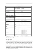
the SYNC_OUT1 pin. Please refer to
Table 2 GPS Port Definition
for more details. Therefore, only
[First Group] is available, and the Second Group cannot be set;
5.
Pulse Trigger Switch:
Turn on /off the “Pulse Trigger Switch” of a specific group of SYNC angle
pulse trigger settings, when “ON” is checked, the settings are activated for editing, when not
checked, the settings turn grey and are not editable.
6.
Pulse Start Angle:
Setting the starting angle, the default value is 0, and the resolution is 0.1
degrees.
7.
Pulse Width:
Setting the pulse width, the default value is 10ms, and the resolution is 20ns,
the maximum duty cycle is 50%;
8.
Pulse Step:
Setting the pulse step pitch, the default value is 360 degrees, and the resolution is
0.05°.
Note:
1. The Device IP and the Destination PC IP must share the same network segment, otherwise the connection
Содержание RS-Helios-1610
Страница 1: ...RS Helios 1610 User Manual RS Helios 1610...
Страница 58: ...RS Helios 1610 User Manual 52 Appendix E Mechanical Drawings...
Страница 60: ...RS Helios 1610 User Manual...


