19
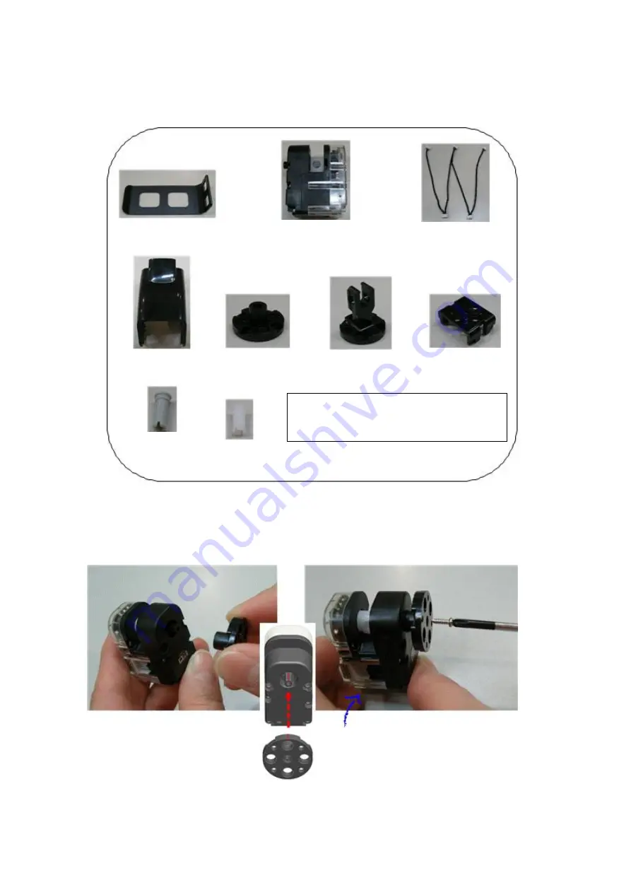
2.3 Right LEG Assembly
STEP1. Insert front horn to smart servo ID09, then fix it with screw (P6).
Before insert front horn to smart servo, check the chase mark as the below.
Foot Frame
Smart Servo * 4
(ID 06, 07, 08, 09)
W Cable * 1
Knee Frame * 1
Front Horn * 1
Joint Frame * 2
‘U’ Frame * 1
3s rivet * 2
2s rivet * 8
Screw (P6) * 1, Bolt (B12) * 1
Bolt(B27)*4, Bolt (B35) *5, NUT * 10
Front
horn
chase
mark
should be in center position
(12 o’clock direction)
Be careful that smart servo initial
position should not be rotated
when you put screw into front
Содержание RQ-110
Страница 1: ......
Страница 12: ...12 1 3 Rivet Tool Rivet Tool Usage ...
Страница 13: ...13 ...
Страница 14: ...14 ...
Страница 15: ...15 ...
Страница 16: ...16 2 RQ HUNO Assembly Guide 2 1 Check Part List Place all the parts as the below for RQ HUNO assembly ...
Страница 28: ...28 STEP8 Connect ID02 and Joint Frame by using 3s rivet Then rotate W Cable two times and connect with ID01 ...
Страница 31: ...31 STEP4 Connect Joint Frame that connected with ID14 and ID15 by using 3s rivet ...
Страница 34: ...34 STEP4 Connect Joint Frame that connected with ID14 and ID15 by using 3s rivet ...
Страница 54: ...54 3 Click Next and finish the installation as shown in the below ...
Страница 60: ...60 Screen Layout This is the screen layout of the MotionBuilder ...
Страница 61: ...61 ...
Страница 65: ...65 9 Move the Jog Dial of ID11 10 For the next movement add the third scene 11 Move the Jog Dial of ID12 ...
Страница 70: ...70 2 Click New Scene to add new scene 3 Click Get Pose you can see Motor Enable window then check Check All ...
Страница 72: ...72 6 Click New Scene to add new scene 7 Click Get Pose you can see Motor Enable window then check Check All ...
Страница 89: ...89 8 3 How to charge ...


