ANALYTICAL COMPUTER GC 9000
.........................................................................................................................................................................................................
...............................................................................................................................................................................................................
Manual EMC 500 · EN01 · 2008-02
26
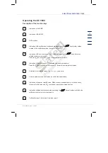
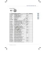
Description of the matrix structure
6
indirect
Input
and one time
right
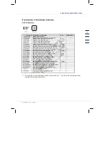
Column U Description of coordinates
Unit
Comment(s)
1 D S2-EMC
Heading EMC sensor 2
2 D S2
EMC sensor 2
mV
3 D S2-in
Input value from EMC sensor 2
mV
1)
4 D S2-Oc
Actual offset sensor 2
mV
6 S S2min
Lower alarm limit EMC sensor 2
mV
7 S S2max
Upper alarm limit EMC sensor 2
mV
14 S S2-af
Averaging factor EMC sensor 2
Bold text shows important fields!
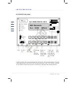
Function key on
the GC 9000
Sequence of key operations to
reach the desired column
Designation of the column A...Y.
The 1st line always contains a
heading
Designation of the line in a
column. The headline is not
displayed in coordinate
representation.
Explanatory notes
on the coordinate
Data protection level:
D = Display value
C = Data which the user can modify
using a code number
S = Data which can be modified via
Abbreviation of the coordinate
(Display of the GC 9000)
Unit of the value displayed or
programmed
Short description of
the coordinate
珠海司福斯特科技有限公司


