background image

15

ENGLISH

On completion of all transport or handling operations, always check the tightness of the water fitting ring nuts.

Take particular care when connecting the unit to the water supply. When tightening a fitting, always hold the opposite 

fitting steady with a second tool to avoid damage.

Connect up the pipes according to the legend on the unit itself and according to the instructions given in this manual. it 

is recommended to minimize the length of  the connection pipes to the buffer storage. 

The following materials are recommended for the construction of the piping system: steel or copper for the primary circuit; 

galvanised steel, copper or hot water compatible plastic for the secondary circuit. Galvanised pipes and fittings must only 

be used in the secondary (DHW) circuit, and care must be taken to avoid electrochemical corrosion.


a

Do not install the unit in gravity feed hot water systems!


b

Make sure that the installation position provides easy visibility of and access to the safety valves.


b

Connect the safety valves to a drain in conformity to applicable standards.


b

Make sure that no obstacles are present between the safety valve and the unit.


b

The diameter of the drain pipe must not be smaller than that of the safety valve’s drain fitting. The drain pipe should 

be no longer than 2 metres and should have no more than two bends in it. If this length has to be exceeded, in-

crease the diameter of the pipe. Never exceed 4 metres and 3 bends.


b

Do not install filters or other restrictions.


b

Make sure that the pipes are watertight before securing them in place.


b

Check that all threaded fittings on the unit are tightened to the correct tightening torque (in case they have worked 

loose during transport).


b

Make sure that the unit is disconnected from the mains power supply before opening the casing of the control panel!

SAFETY WARNINGS


b

The unit can become hot enough to cause burns if touched.


b

In the event of a power failure, the motorised control valve could remain in the open position, causing the whole 

system to become hot enough to cause burns if touched.


b

Water in the unit can be very hot and under pressure. Therefore, before performing any work, always drain the unit 

and close the shut-off valves on the primary and secondary circuits.


b

The unit must be installed and put into service in strict conformity to all laws and standards applicable in the place 

of installation, and according to best professional practices.

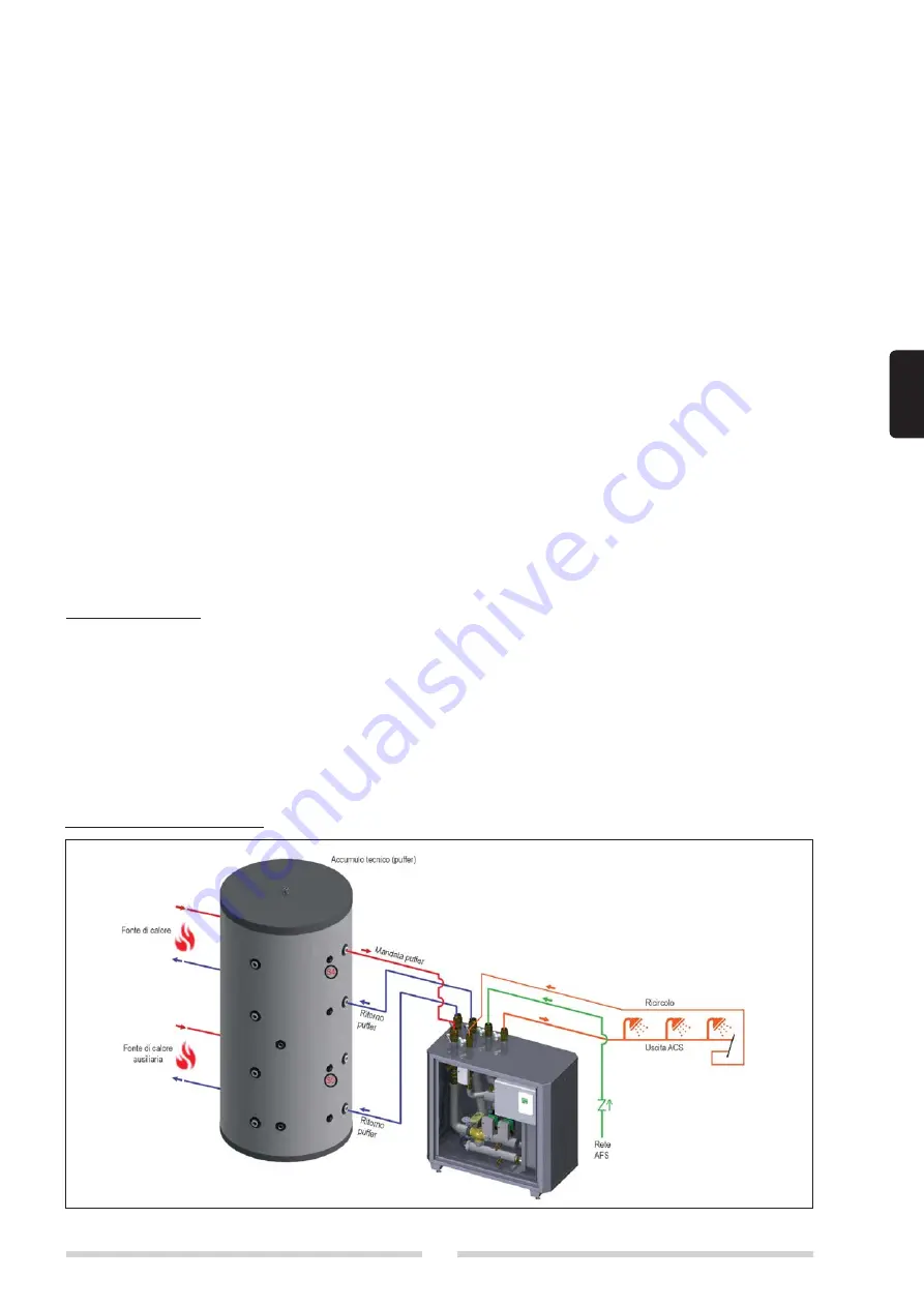
EXAMPLE OF INSTALLATION 

Содержание SC ACS 160

Страница 1: ...al energy sources such as solar energy heat pumps biomass etc The module has been designed integrating the most advanced hydraulic and electronic control technologies ensuring the production of DHW up to 220 l min per module Description Q ty 1 DHW mixer in packing 1 2 Instruction manual 1 3 Circulation pump assembling instructions 1 4 DHW return pump assembling instructions 1 5 Fuse 1 DESCRIPTION ...

Страница 2: ...f the prod uct or from the use of non original spare parts b Do not expose the product to the elements It is not designed for use outdoors ELECTRICAL CONNECTIONS The controller must be installed and connected by authorized staff according to applicable regulations Connect the power supply to the control unit complete with bipolar switch fuses power 230Vac 50Hz It is essential to connect the proper...

Страница 3: ...e 5 Primary circuit mixer valve with servomotor 220 V AC 3 positions 6 High efficiency modulating pumps 1 and 2 installed in parallel 7 Automatic vent valve 8 Double return diverter valve 9 Primary circuit shut off ball valve 10 Filling drain cock 1 2 M Secondary circuit 11 Digital flow and temperature meter 5 100 l min 10 200 l min 12 Filter 13 Anti pressure surge ball valve 14 Circulation pump 1...

Страница 4: ...S2 S6 5 5 5 1 Shut off valve 2 Y filter 3 Three way mixer valve 4 Modulating pump 5 Non return valve 6 Heat exchanger 7 Flow meter with temperature sensor S5 S6 8 Three way diverter valve 9 Vent valve 10 Drain valve 11 Non return valve recommended not supplied Double return variant ...

Страница 5: ...imum operating pressure primary circuit 10 10 bar Maximum operating pressure secondary circuit 10 10 bar Consumption 410 770 W Power supply voltage 230 230 V Index of protection 40 40 IP Primary circuit pumps Wilo STRATOS PARA 25 1 8 Wilo STRATOS PARA 25 1 12 Overall dimensions b x h x p 900 x 1000 x 500 mm Overall dimensions b x h x p 1050 x 1225 x 580 mm SECONDARY CIRCUIT PRESSURE LOSS P1 P2 P1 ...

Страница 6: ...3 0 50 0 67 0 83 1 00 1 17 1 33 1 50 1 67 1 83 2 00 2 17 2 33 2 50 2 67 2 83 3 00 3 17 3 33 3 50 3 67 3 83 4 00 4 17 4 33 l sec 10 42 C 10 45 C 10 48 C 10 50 C 10 55 C 10 60 C DHW flow rate l min Temperature of water from storage cylinder C DHW RETURN PRESSURE LOSS P3 P2 0 1 2 3 4 5 6 7 8 9 10 mH 2 O l h 0 0 1000 2000 3000 4000 5000 P3 P2 10 20 30 40 50 60 70 80 90 100 kPa Wilo stratos para z 25 1...

Страница 7: ...0 2 67 2 83 3 00 3 17 3 33 3 50 3 67 3 83 4 00 4 17 4 33 l sec NB The proper working of the module is assured if the supply temperature of the primary circuit is at least 3 C greater than the DHW temperature set DHW flow rate l min Temperature of water from storage cylinder C PRIMARY CIRCUIT PUMP CHARACTERISTICS 0 0 1 2 3 4 5 6 7 8 9 10 11 12 2 4 6 8 10 12 14 Flow m h Head m Stratos PARA 15 20 25 ...

Страница 8: ...bottom of storage cylinder 1 1 2 RP2 Primary outlet 2 middle of storage cylinder 1 1 2 MP Primary inlet 1 1 2 RS DHW circulation inlet 1 1 4 EAFS Domestic cold water inlet 1 1 4 UACS Domestic hot water outlet 1 1 4 Dimensions Height 1140 mm Width 1000 mm Depth 500 mm Install the unit with at least 50 cm free access all around it to permit inspection and mainte ...

Страница 9: ...9 ENGLISH WIRING DIAGRAM ...

Страница 10: ...rcolo Mandata primario EAF Fonte di calore Uscita ACS Ricircolo Mandata primario OFF ON Boiler Boiler DHW outlet DHW outlet Recirculation Recirculation Cold water inlet Cold water inlet Primary inlet Primary inlet Single return variant Double return variant ...

Страница 11: ...s In the event of a malfunction in either of the DHW pumps the unit automatically adjusts itself to deliver up to 60 of the hot water requested The unit is designed to make replacement of the controller as easy as possible The controller is located inside the IP55 electrical control panel C1 C2 CR G Legend G Main switch C1 Pump 1 C2 Pump 2 CR Circulation pump ...

Страница 12: ...he product from the mains power supply before commencing any work on it b The product must be installed in conformity to the laws and standards applicable in the country of installation b The manufacturer s responsibility ends with the supply of the product The product must be installed in accordance with industry standards by suitably qualified persons working for a company that will assume full ...

Страница 13: ... The product must be stored in a dry place where it is not subject to frost The product must be installed where it is protected against splashes of water Ambient temperature in the place of installation must not exceed 40 C during functioning of the product b It is advisable to install the product as near as practically possible to the storage cylinder in order to avoid unnec essary heat loss from...

Страница 14: ...l 30 Free chlorine mg l 0 5 Hydrogen sulphide mg l 0 05 Ammonia mg l 2 Bicarbonate mg l 300 Bicarbonate Hydrogen sulphide mg l 1 0 Sulphur mg l 1 Nitrate mg l 100 Nitrite mg l 0 1 Sulphate mg l 100 Manganese mg l 0 1 Dissolved iron mg l 0 2 Free aggressive car bon dioxide mg l 20 In presence of water with hardness above 15 Fr is pre scribed an appropriate treatment of the heating water in order to...

Страница 15: ...safety valve and the unit b The diameter of the drain pipe must not be smaller than that of the safety valve s drain fitting The drain pipe should be no longer than 2 metres and should have no more than two bends in it If this length has to be exceeded in crease the diameter of the pipe Never exceed 4 metres and 3 bends b Do not install filters or other restrictions b Make sure that the pipes are ...

Страница 16: ...any circumstances dispose of the controller with ordinary household refuse Dispose of the controller only at designated collection points or return it to the dealer or manufacturer b The manufacturer declines all responsibility for damage caused by failing to ground the product adequately or by failure to respect the wiring diagrams provided in this manual PRIMARY CIRCUIT FILLING PROCEDURE b Fill ...

Страница 17: ... access menu 3 OPERATING MODE and press OK then activate MANUAL FUNCTION in menu 3 2 use the or selector to move to function V3 1st pri mary circulator and activate by pressing the OK key Leave the circulator active for at least 20 seconds to eliminate the residual air inside the circuit use the or selector to move to function V4 2nd pri mary circulator and repeat the operation as described above ...

Страница 18: ...re not in perfect condition must be exchanged immediately Use only original spare parts and accessories from the manufacturer Markings made on the unit at the factory must not be altered removed or made illegible Only the settings described in these instructions may be set using the Unit b Changes to the unit can compromise the safety and function of the unit or the entire system ABOUT THE CONTROL...

Страница 19: ... with S4 temperature probe high puffer already wired to the electrical panel to be connected to the puffer as shown in fig 6 S5 PROBE POSITIONING ONLY WITH DIVERTER KIT If BIG T FAST ie is equipped with a diverter valve primary return kit the S5 probe low puffer must be connected in sup plied and already wired to the electrical panel in the lower part of the puffer as shown in fig 6 Temperature re...

Страница 20: ...X BOX 1 CAN high 1 CAN high 4 Power supply 5 S6 Storage transfer 2 CAN low 2 CAN low 3 GND 4 S7 Solar 2 l min 3 S8 not used optionally 1 Temp C 2 V4 additional pump PWM signal 1 GND ON THE CONTROLLER BOX VFS CAN CAN ...

Страница 21: ...tting MENU SEQUENCE AND MENU STRUCTURE Schematic or overview mode will appear if no key is pressed for a period of 2 minutes or if esc is pressed to exit the main menu Pressing any key in schematic or overview mode the main menu reappears The following menus are available Exit main menu OK esc 1 Measurements 2 Statistics 1 Measured values Measured sensor values 2 Statistics Operating hours counter...

Страница 22: ...s all values Menu 5 Protection Functions if any adjustments necessary Menu 6 Special Functions if any adjustments necessary In menu operating mode 3 2 Manual test the switch outputs with the consumers connected and check the sensor values for plausibility Then set to automatic mode b Observe the indications for individual parameters given on the following pages and check whether or not further set...

Страница 23: ...data be ing cleared recorded incorrectly or overwritten The manufacturer accepts no liability for the recorded data Operating hours Display of operating hours of the relays connected to the controller Heat quantity Display of the consumed heat quantity form the system in kWh This is an indicative value Graphic overview This results in a clear illustration of the data as a bar graph Different time ...

Страница 24: ...controller replace the safety appliances on site Tset Setpoint temperature at the flow sensor The LFWC controller operates on the condition that the hot water temperature tap temperature measured at the flow sensor is adjusted as quickly as possible and kept constant Tmax Maximum hot water tap temperature measured at the flow sensor Exceeding this limit will cause the pump to be switched off If th...

Страница 25: ...ature Once the pump in the primary circuit stops the setpoint temperature is raised to the set Tset again When the storage sensor is connected If the temperature at the storage sensor is smaller than Tset 5 C the target temperature is lowered to the currently meas ured storage temperature 5 C In both cases Circ Tmin is set to the new setpoint Circ Hysteresis 5 K Here too the newly calculated value...

Страница 26: ...g the flushing or manual operation Show signal Represents the set pump signal in a graphic and text overview Relay functions for free relays Free i e in the hydraulic variant unused relays can be assigned to various additional functions Every additional function can only be assigned once All special functions which function values can be preset and changed also appear in the menu Settings as soon ...

Страница 27: ...ge temperature drops below Min Storagetemp Tap support calibration For information about the function and calibration procedure See Calibration of Tap Support on page 11 Storage Heating To heat up the storage on demand the necessary parameters can be set here Activate or deactivate function Minimum storage temperature If this value falls below this value at the associated storage sensor outside th...

Страница 28: ...imary circuit is switched on to support the primary pump When the measured flow rate exceeds flow rate on and if this conditions is met throughout the period delay the relay is switched on Activate or deactivate function Flow on Adjustable flow rate in l h at which the additional pump is switched on Flow off Adjustable flow rate in l h at which the additional pump is switched off Delay The additio...

Страница 29: ...ivated by a technician if problems occur with the measurement recording Observe in particular the instructions from the collector manufacturer The menus Purging time and Increase are only displayed when the starting aid function is set to On Purging time If the temperature on the collector sensor increases within a minute by the value defined under increase the solar circu lation pump will be turn...

Страница 30: ...be activated DF Station Here the upper flow limit is set in of the DF sensor If this limit is exceeded an additional station from the cascade is requested b If the currently running station does not reach the set tapping temperature despite 100 speed of the primary pump a further station is automatically requested DF Station Here the bottom flow limit is set in of the flow sensor If the flow falls...

Страница 31: ...nu you can adjust which pressure sensor is being used Please note If e g VFS1 is connected RPS1 option is not shown Pmin Minimum pressure If this pressure is not met the controller emits an error notification and the red LED flashes Pmax Maximum pressure in the system If this pressure is exceeded the controller emits an error message and the red LED flashes Sensor Calibration Deviations in the tem...

Страница 32: ...tor or respectively the data logger Your user name is going to appear in this menu and can be selected and confirmed with OK Note You can find the address of the connector or respectively the data logger on the address sticker on the outside of the casing Pointers and help on how to establish a connection you can find in the enclosed connect instructions or the instructions of the data logger Sele...

Страница 33: ...ccessible despite the menu lock being activated and can be used to make adjustments if necessary 1 Measurement values 2 Statistics 4 Settings 6 Special Functions 7 Menu lock 9 Language 8 SERVICE VALUES Serve for remote diagnosis by a specialist or the manu facturer in the event of errors etc b Enter the values into the table when an error occurs 9 LANGUAGE To select the menu language During initia...

Страница 34: ...le adjusted Frequent on off A relay was switched on and off more than 5 times within 5 minutes Anti legionella failed Anti legionella failed appears if at least anti legionella Tsoll 5 C could not be held at the antilegionella sensor for the set exposure time Primary pump defect Is displayed if flow is recognized but Tset is not reached and the flow tempera ture did not rise up 3 K in 3 seconds Th...

Страница 35: ...t Exchange the defective fuse for a new one locate the external source of the error e g pump and exchange it Then first recommission the controller and check the function of the switch outputs in manual mode MAINTENANCE b In the course of the general annual maintenance of your heating system the functions of the controller should also checked by a specialist and the settings should be optimized if...

Страница 36: ... IF 6 12 2 1 ON 4 15 Thermostat 4 15 1 T min storage 10 85 C 50 C 50 C 4 15 2 T set storage 45 95 C 55 C 55 C 4 15 3 Hysteresis 1 30 C 5 C 5 C 4 15 4 Thermostat periods Period therm set tings Period therm settings SEE 6 9 4 16 Zone valve 4 16 1 DT return stora ge 1 20 C 3 C 3 C 4 17 Additional pump 4 17 1 Flow rate ON 20 200 l min 50 l min 70 l min 4 17 2 Flow rate Off 10 60 l min 30 l min 40 l mi...

Страница 37: ...off 6 SPECIAL FUNCTIONS PRIMARY CIR CULATION 6 1 v1 signal 6 1 1 Signal type 0 10V PWV PWM PWM 6 1 2 Signal setting MANUAL MANUAL 6 1 3 Output signal Normal inverted INVERTED INVERTED 6 1 4 PWM off 0 15 98 98 6 1 5 PWM on 2 50 87 87 6 1 6 PWM max 50 100 7 7 6 1 7 show signal 6 2 V1 speed 6 2 2 Purging type 6 600 s 8 s 8 s 6 2 3 Regulation time 1 15 min 1 min 1 min 6 2 4 MAX speed 15 100 100 100 6 ...

Страница 38: ...T return stora ge 1 20 C 3 C 3 C 6 9 4 Anti legionella 6 9 5 Error message 6 9 6 Additional pump 6 9 7 solare 6 9 8 Parallel operat V1 6 9 9 Parallel operat V2 V2 6 9 10 Always on 6 9 11 Cascade 6 10 Relay 2 6 10 1 recirculation 6 10 2 thermostat 6 10 3 Zone valve 6 10 4 Anti legionella 6 10 4 1 Ant ilegionella on off off off 6 10 5 Error message 6 10 6 Additional pump 6 10 7 solar 6 10 8 Parallel...

Страница 39: ...ror message 6 12 6 Additional pump 6 12 7 solar 6 12 8 Parallel operat V1 6 12 9 Parallel operat V2 V2 6 12 10 Always on 6 12 11 Cascade DESCRIZIONE MENU DESCRIPTION SETTINGS RAN GE DEFAULT SC ACS 160 DEFAULT SC ACS 225 NOTE 6 SPECIAL FUNCTIONS RECIRCULA TION 6 13 Signal V1 Recirculation Recirculation 6 13 1 Recirculation 6 13 1 1 Recirculation on off on on 6 13 1 2 Contin Recirc Function Request ...

Страница 40: ...14 8 Solar 6 14 9 Always on 6 14 10 Cascade 6 15 Signal V2 6 15 1 Recirculation 6 15 2 thermostat 6 15 3 Zone valve 6 15 4 Anti legionella 6 15 5 Errore mes sage 6 15 6 Additional pump 6 15 6 1 Additional pump on off on on 6 15 6 2 Flow rate on 20 200l min 50l min 70l min 6 15 6 3 Flow rate off 10 60l min 30l min 40l min 6 15 6 4 Delay 1 60s 3s 3s 6 15 7 Primary mixer 6 15 8 Solar 6 15 9 Always on...

Страница 41: ...nstant flow rate 100 100 0 0 6 18 Commissioning yes no 6 19 Factory setting yes no 6 20 Time Date 6 21 Daylight saving yes no Si Si 6 22 ECOmode display on off on on 6 23 temperatura unit C F C C 6 24 Network 7 MENU LOCK 7 1 Menù lock on off on on 7 2 expert mode expert simple simple simple Control unit sofware 1330572V ...

Страница 42: ...he table below DESCRIPTION OK All automatic or manual filling pumps removed Safety valve calibrated to 6 bar and flow open Drain pipe from safety valve routed suitably Expansion vessel correctly located and pre charged to 2 5 bar Non return valves activated as gravity brakes ...

Страница 43: ...43 ENGLISH ...

Страница 44: ...045 Legnago VR The manufacturer strives to continuously improve all products Appearance dimensions technical specifications standard equipment and accessories are therefore liable to modification without notice cod Doc 0100463 Rev 1 06 2021 ...

Отзывы: