20045163
14
GB
Technical description of the burner
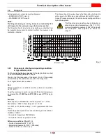
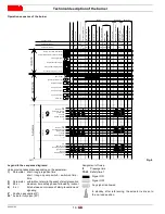
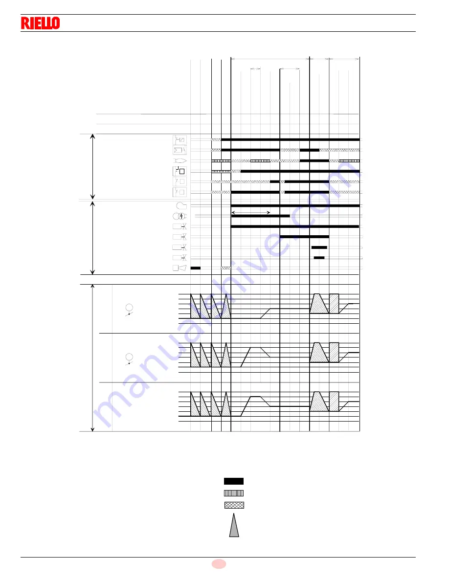
Operation sequence of the burner
Legend to the sequence diagrams:
Valve proving takes place depending on the parameter:
1)
Parameter: short / long preignition time
short / long oil pump switch - switch-on time -
time
3)
Parameter: with/without alarm in the event of start prevention
5)
28 s =
maximum time safety phase, followed by lockout
6)
5 s =
time between occurrence of start prevention and
signaling
0°
Position as supplied (0°)
90° Actuator fully open (90°)
Assignment of times:
t1
Prepurge time
TSA1 Safety time 1
00
02
12
22
24
30
36
38
40
42
44
60
62
70
72
74
3)
TSA1
t1
p
a
T
P
P
T
1)
10
217
211
214 264
265
266 267
269 268
270
212
273
274
217
28 s
5 s
5)
6)
Shutdown
Operation
Startup
L
K
=
>
Z
-
PO
S
Pre
ig
n
it
io
n
Z
=
O
N
BV
=
O
N
Z
=
O
F
F
In
te
rva
l
1
t
4
4
O
p
e
ra
ti
o
n
1
(st
a
ti
o
n
a
ry)
O
p
e
ra
ti
o
n
2
L
K
=
>
K
-
P
O
S
C
o
mb
in
e
Po
st
b
u
rn
t
ime
t
1
3
Sa
fe
ty
p
h
a
se
St
a
n
d
b
y
(st
a
ti
o
n
a
ry)
M
=
O
N
,
SV=
IN
L
K
=
>
BV
-
PO
S
Po
st
p
u
rg
e
t
ime
t
8
L
K
=
>
N
-
PO
S
L
o
cko
u
t
p
h
a
se
H
o
me
ru
n
Pre
p
u
rg
e
OU
TP
U
T
S
IN
P
U
T
S
Phase number
F
u
e
l
Act
u
a
to
r
2
Ai
r
Act
u
a
to
r
1
A
c
tu
a
to
rs
Parameter number
Parameter number
Safety limit thermostat (STB)
Control thermostat or pressurestat (R)
Flame signal (FS)
Air pressure switch (LP)
Pressure switch-min (Pmin)
Pressure switch-max (Pmax)
No-load position
Ignition load
Postpurge position
Nominal load
Low-fire
90°
0°
VSD
Motor (M)
Ignition transformer (Z)
Alarm (AL)
Safety valve (SV)
Fuel valve 1 (V1)
Fuel valve 2 (V2)
Fuel valve 3 (V3)
No-load position
Ignition load
Postpurge position
Nominal load
Low-fire
90°
0°
No-load position
Ignition load
Postpurge position
Nominal load
Low-fire
90°
0°
Fig. 8
S8470
Signal ON
Signal OFF
Any signal is allowed
In standby: after referencing, the actuator is driven to
the no-load position
Содержание RL 70/E
Страница 2: ......
Страница 35: ...Appendix Spare parts 33 20045163 GB A Appendix Spare parts 74 75 76 80 ...


