background image

Information and general instructions


20045163

GB

1.1

Information about the instruction manual

1.1.1

Introduction

The instruction manual supplied with the burner:

is an integral and essential part of the product and must not be
separated  from  it;  it  must  therefore  be  kept  carefully  for  any
necessary consultation and must accompany the burner even
if it is transferred to another owner or user, or to another sys-
tem. If the manual is lost or damaged, another copy must be
requested from the Technical Assistance Service of the area;

is designed for use by qualified personnel;

offers  important  indications  and  instructions  relating  to  the
installation  safety,  start-up,  use  and  maintenance  of  the
burner.

Symbols used in the manual

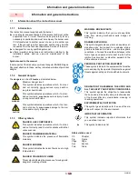
In some parts of the manual you will see triangular DANGER signs.
Pay great attention to these, as they indicate a situation of potential
danger.

1.1.2

General dangers

The dangers can be of 3 levels, as indicated below.

1.1.3

Other symbols

Abbreviations used

Ch.

Chapter

Fig.

Figure

Page

Page

Sec.

Section

Tab.

Table

1

Information and general instructions

DANGER

Maximum danger level!
This symbol indicates operations which, if not car-
ried  out  correctly,  cause  serious  injury,  death  or
long-term health risks.

WARNING

This symbol indicates operations which, if not car-
ried out correctly, may cause serious injury, death
or long-term health risks.

CAUTION

This symbol indicates operations which, if not car-
ried  out  correctly,  may  cause  damage  to  the  ma-
chine and/or injury to people.

DANGER

DANGER: LIVE COMPONENTS

This symbol indicates operations which, if not car-
ried out correctly, lead to electric shocks with lethal
consequences.

DANGER: FLAMMABLE MATERIAL

This  symbol  indicates  the  presence  of  flammable
materials.

DANGER: BURNING

This symbol indicates the risks of burns due to high
temperatures.

DANGER: CRUSHING OF LIMBS

This symbol indicates the presence of moving parts:
danger of crushing of limbs.

WARNING: MOVING PARTS

This  symbol  indicates  that  you  must  keep  limbs
away  from  moving  mechanical  parts;  danger  of
crushing.

DANGER: EXPLOSION

This symbol signals places where an explosive at-
mosphere  may  be  present.  An  explosive  atmos-
phere is defined as a mixture - under atmospheric
conditions - of air and flammable substances in the
form of gases, vapours, mist or dust in which, after
ignition  has  occurred,  combustion  spreads  to  the
entire unburned mixture.

PERSONAL PROTECTION EQUIPMENT

These symbols indicate the equipment that must be
worn and kept by the operator for protection against
threats against safety and/or health while at work.

OBLIGATION  TO  ASSEMBLE  THE  HOOD  AND
ALL THE SAFETY AND PROTECTION DEVICES

This  symbol  signals  the  obligation  to  reassemble
the hood and all the safety and protection devices
of  the  burner  after  any  maintenance,  cleaning  or
checking operations.

ENVIRONMENTAL PROTECTION

This symbol gives indications for the use of the ma-
chine with respect for the environment.

IMPORTANT INFORMATION

This  symbol  indicates  important  information  that
you must bear in mind.

This symbol indicates a list.

Содержание RL 70/E

Страница 1: ...20045163 4 11 2014 Installation use and maintenance instructions Light oil burner Modulating operation CODE MODEL 20045065 RL 70 E GB ...

Страница 2: ......

Страница 3: ...ng rate 9 3 9 1 Procedure to refer burner operating condition in high altitude plants 9 3 10 Minimum furnace dimensions 11 3 11 Control box for the air fuel ratio LMV37 4 12 3 12 Actuators SQM33 5 15 4 Installation 16 4 1 Notes on safety for the installation 16 4 2 Handling 16 4 3 Preliminary checks 16 4 4 Operation position 16 4 5 Combustion head pre setting 17 4 6 Securing the burner to the boil...

Страница 4: ...e first start up 26 5 2 Burner calibration 26 5 3 Adjusting the nozzle flow rate 26 5 3 1 Pressure controller 26 5 4 Burner start up 27 5 5 Final calibration of the pressure switch 28 5 5 1 Air pressure switch 28 5 6 Flame signal measurement 28 5 7 Final checks with the burner working 29 6 Maintenance 30 6 1 Notes on safety for the maintenance 30 6 2 Maintenance programme 30 6 2 1 Maintenance freq...

Страница 5: ... car ried out correctly may cause damage to the ma chine and or injury to people DANGER DANGER LIVE COMPONENTS This symbol indicates operations which if not car ried out correctly lead to electric shocks with lethal consequences DANGER FLAMMABLE MATERIAL This symbol indicates the presence of flammable materials DANGER BURNING This symbol indicates the risks of burns due to high temperatures DANGER...

Страница 6: ... of damage to things or injury to peo ple if such damage injury was due to any of the following causes incorrect installation start up use and maintenance of the burner improper incorrect or unreasonable use of the burner intervention of unqualified personnel carrying out of unauthorised modifications on the equipment use of the burner with safety devices that are faulty incorrectly applied and or...

Страница 7: ...ance Only those parts envisaged by the manufacturer can be replaced 2 2 Personnel training The user is the person body or company that has acquired the ma chine and intends to use it for the specific purpose He is responsi ble for the machine and for the training of the people working around it The user undertakes to entrust the machine exclusively to suitably trained and qualified personnel under...

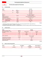
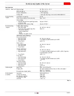
Страница 8: ...Low high or modulating Nozzle number 1 return flow nozzle Standard applications Boilers water steam thermal oil Ambient temperature F 32 104 0 40 C Combustion air temperature F max 140 60 C Pump delivery at 290 PSI pressure range fuel temperature GPH PSI F max 60 8 145 304 5 194 90 C Noise levels 3 dB A 78 5 Model RL 70 E Control circuit power supply V Ph Hz 120 1 60 Main electrical supply 10 V Ph...

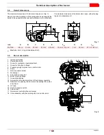
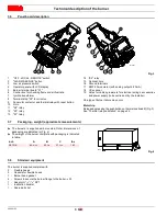
Страница 9: ...ment 4 Screw for fixing fan to flange 5 Pressure gauge for pressure on nozzle return 6 Pump 7 Non drip nozzle holder 8 Air damper 9 Fan pressure test point 10 Boiler mounting flange 11 Flame stability disk 12 Servomotor provides adjustment of fuel delivery regulator 13 Slide bars for opening the burner and inspecting the combu stion head 14 HT lead 15 High oil pressure switch 16 Fan air inlet 17 S...

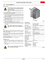
Страница 10: ...or electrical wirings accessories and power supply to be carried out by the installer One type of burner failure may occur Motor trip Release by pressing the pushbutton on thermal overload 9 Fig 3 See Thermal relay calibration on page 24 3 7 Packaging weight approximate measurements The burners is supplied skid mounted Outer dimensions of packaging are indicated in Fig 4 The weight of the burner c...

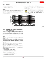
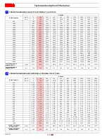
Страница 11: ...of the burner Fig 5 if the working point defined by the values above is within the range limits If not higher burner size is needed Note Charts are based only on altitude variation reference temperature 68 F 20 C To get the combined correction in case of different air temperature a compensation of 1000 ft each 20 F 305 m each 11 C is appli cable Example Rated capacity 3000 MBtu hr Rated air pressu...

Страница 12: ... 8 908 2 875 8 843 5 811 85 779 8 747 8 Average barometric pressure 68 F w c 399 394 385 371 358 345 332 320 307 294 CORRECTED BURNER AIR PRESSURE ACCORDING TO ALTITUDE Altitude Rated Pressure m a s l 0 100 305 610 915 1220 1525 1830 2135 2440 ft a s l 0 328 1000 2000 3000 4000 5000 6000 7000 8000 0 50 0 49 0 50 0 51 0 53 0 55 0 57 0 59 0 62 0 64 0 67 1 00 0 99 1 00 1 02 1 06 1 10 1 14 1 19 1 23 1...

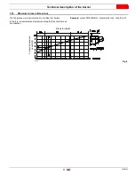
Страница 13: ...ce dimensions The firing rates were set in relation to certified test boilers In the Fig 6 indicates the diameter and length of the test combus tion chamber Example output 2579 MBtu hr diameter 24 inch length 6 6 ft Fig 6 Diameter inch Length ft Furnace dimensions D2919 ...

Страница 14: ...f the air and fuel circuits via which it is possible to easily identify any causes of malfunctioning Mechanical design The following system components are integrated in the LMV37 4 basic unit Electronic air fuel ratio control Control frequency converter air fan Modbus interface Installation notes Always run high voltage ignition cables separately while observ ing the greatest possible distance to ...

Страница 15: ...l voltage Nominal current Power factor AC 120 V 50 60 Hz 1 6 A pilot duty load declaration to UL372 cosϕ 0 4 Alarm output Nominal voltage Nominal current Power factor AC 120 V 50 60 Hz 1 A cosϕ 0 4 Ignition transformer Nominal voltage Nominal current Power factor AC 120 V 50 60 Hz 1 6 A pilot duty load declaration to UL372 or 250 VA ignition load declaration to UL372 cosϕ 0 2 Fuel valves Nominal v...

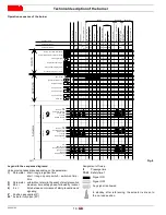
Страница 16: ... ON BV ON Z OFF Interval 1 t44 Operation 1 stationary Operation 2 LK K POS Combine Postburn time t13 Safety phase Standby stationary M ON SV IN LK BV POS Postpurge time t8 LK N POS Lockout phase Homerun Prepurge OUTPUTS INPUTS Phase number Fuel Actuator 2 Air Actuator 1 Actuators Parameter number Parameter number Safety limit thermostat STB Control thermostat or pressurestat R Flame signal FS Air ...

Страница 17: ...on the dis play of the Operator Panel Index 0 for fuel actuator index 1 for air actuator Installation notes Always run the high voltage ignition cables separate from the unit and other cables while observing the greatest possible dis tance The holding torque is reduced when the actuator is disconnect ed from power Technical data Tab E WARNING To avoid injury to persons damage to property or the en...

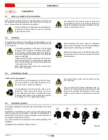
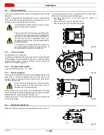
Страница 18: ...n force WARNING The handling operations for the burner can be highly dangerous if not carried out with the greatest atten tion keep any unauthorised people at a distance check the integrity and suitableness of the available means of handling Check also that the area in which you are working is empty and that there is an adequate escape area i e a free safe area to which you can quickly move if the...

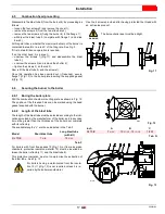
Страница 19: ...duct 4 6 Securing the burner to the boiler 4 6 1 Boring the boiler plate Drill the combustion chamber mounting plate as shown in Fig 12 The position of the threaded holes can be marked using the head gasket supplied with the burner 4 6 2 Length of the blast tube The length of the blast tube must be selected according to the indi cations provided by the manufacturer of the boiler and in any case it...

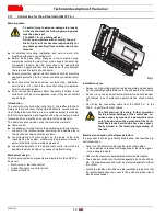
Страница 20: ...o prevent the flame stability disk from pressing against the blast tube Tighten the screws 1 on the slide bars 2 and screws 4 fixing the burner to the flange If it proves necessary to change a nozzle with the burner already fitted to the boiler proceed as outlined below Pull back the burner on its slide bars as shown in Fig 13 page 17 Remove the nuts 1 Fig 16 and the disk 2 Use wrench 3 Fig 16 to ...

Страница 21: ... operating Turn screw 4 Fig 18 until the notch shown in diagram Fig 19 is level with the front surface of flange 5 Fig 18 Example maximum light oil delivery 16 GPH Diagram Fig 19 indicates that for a delivery of 16 GPH requires the combustion head to be set to approx three notches as shown in Fig 18 Fig 18 D462 N Notches Max Fuel oil delivery GPH D12159 Fig 19 ...

Страница 22: ...s of a loop of piping exiting and returning to the tank with an auxiliary pump that circulates the fuel under pressure A branch connection from the loop goes to feed the burner This cir cuit is extremely useful whenever the burner pump does not suc ceed in self priming because the tank distance and or height difference are higher than the values listed in the Tab H Tab H Key H Pump foot valve heig...

Страница 23: ...ot be stepped on or come into contact with hot surfaces of the boiler Now connect the other end of the hoses to the suction and return lines 4 11 1 Oil hydraulic system layout 1 Pump suction 2 Solenoid valve 3 Pump 4 Pressure regulator 5 Return pipe 6 By pas screw 7 Pump return 8 Solenoid valve 9 Solenoid valve 10 Piping 11 Filter 12 Piping 13 Pressure regulator 14 Servomotor M Pressure gauge P Oi...

Страница 24: ...out wait approx 15 sec onds reset the burner and then repeat the starting operation as of ten as required After 5 or 6 starting operations allow 2 or 3 minutes for the transformer to cool PUMP SUNTEC J7 C A GPH 60 8 B PSI 145 304 5 C Hg 13 D cSt 2 8 200 E F 194 90 C F PSI 21 8 G PSI 290 H inch 0 006 WARNING Before starting the burner make sure that the tank return line is not clogged Obstructions ...

Страница 25: ...ifications or connections different from those shown in the electri cal layouts Check that the electrical supply of the burner corresponds to that shown on the identification label and in this manual Do not invert the neutral with the phase in the electrical supply line Any inversion would cause a lockout due to firing failure The electrical safety of the device is obtained only when it is correct...

Страница 26: ...s a nominal value To reset in the case of an intervention of the thermal relay press the button RESET Fig 25 The button STOP Fig 25 opens the NC 95 96 contact and stops the motor To test the thermal relay insert a screwdriver in the window TEST Fig 29 and move it in the sense of the arrow towards right 4 14 2 Electronic thermal relay To reset in the case of an intervention of the thermal relay pre...

Страница 27: ...f voltage maintenance or substitu tion Fig 30 IE1 IE2 Epact U2 V2 W2 U3 V3 W3 U1 V1 W1 S8379 U2 V2 W2 U3 V3 W3 U1 V1 W1 S8380 460V 208 230V 460V 208 230V D3686 WARNING The motors manufactured for 575V IE2 Epact voltage have the same control box base of the IE1 motors Please pay attention to the indications in case of maintenance or substitution Fig 31 575V S8382 WARNING If it is necessary to rever...

Страница 28: ...livery and nozzle return must be at least 43 5 PSI With smaller pressure differences the pressure on the nozzle return can be unstable 5 3 1 Pressure controller 1 Gauge for pressure in return line 2 Oil pressure switch 3 Ring for piston stop 4 Nut and lock nut for piston setting 5 Eccentric adjusting screw 6 Variable eccentric 7 Eccentric locking screws The nozzle return pressure value is indicate...

Страница 29: ...the RWF 40 regulator Please refer to the spacific manual for this operation Turn the switch of Fig 35 to position LOCAL WARNING the proper setting of the eccentric 6 is possible when its operation field follows the servomotor op eration field 20 130 so that every variation of the servomotor position corresponds to a pressure variation WARNING Do not let the piston bottom out repeatedly the stop ri...

Страница 30: ... the knob counter clockwise about 20 of the set point and start up the burner again to ensure the set point is correct If the burner locks out again turn the knob counter clockwise a little bit more 5 6 Flame signal measurement Check the flame signal through the parameter 954 as indicated in Fig 38 The displayed value is expressed in percentage The value during the operation must be higher than 24...

Страница 31: ...scale position Rotate the maximum oil pressure switch at the minimum of the scale The burner must stop in lockout Switch off the burner and disconnect the voltage Rotate the minimum low oil pressure switch at the maximum of the scale The burner must not start Cover the UV flame sensor The burner must stop in lockout due to firing failure WARNING Make sure that the mechanical locking systems on the...

Страница 32: ...es Fan Check to make sure that no dust has accumulated inside the fan or on its blades as this condition will cause a reduction in the air flow rate and provoke polluting combustion Flame inspection window Clean the glass Fig 39 Photocell Clean the glass cover from any dust that may have accumulated Photocell 1 Fig 40 can be removed by pulling it outward forceful ly 6 Maintenance DANGER The mainte...

Страница 33: ...piping Nozzle It is advisable to replace nozzles once a year during periodical maintenance Do not clean the nozzle openings Filters Check the following filters on line 1 in pump 2 at nozzle 3 and clean or replace as required If rust or other impurities are observed inside the pump use a sep arate pump to suck out any water and other impurities that may have deposited on the bottom of the tank Flex...

Страница 34: ...llowing the steps described but in reverse order refit all burner components as they were originally assembled DANGER Disconnect the electrical supply from the burner by means of the main system switch DANGER Close the fuel interception tap WARNING Wait for the components in contact with heat sourc es to cool down completely D1233 Fig 43 WARNING Carry out all maintenance work and mount the cas ing...

Страница 35: ...Appendix Spare parts 33 20045163 GB A Appendix Spare parts 74 75 76 80 ...

Страница 36: ...RING 21 3013259 BEARING 22 3012384 OIL PRESSURE SWITCH C 23 3009080 CONNECTOR C 24 3006140 PRESSURE GAUGE 25 3007169 O RING B 26 3003006 CONNECTOR C 27 3006723 CONNECTOR C 28 3012455 RACCORDO C 29 3007164 SEAL B 30 3006369 PUMP C 31 3006184 CONNECTOR C 32 3012946 MODULATOR B 33 20034545 CORE 34 3003001 COIL B 35 3009081 CONNECTOR C 36 3013929 AIR DAMPER 37 3003954 DRIVE COUPLING A 38 3003952 SOUND...

Страница 37: ...LATOR 58 3013925 VIEWING PORT 59 3014079 SPACER 60 3013922 INSPECTION WINDOW 61 3012939 FAN C 62 3013938 DRIVE DISK JOINT 63 3003204 SEAL B 64 3003294 O RING B 65 3012622 DRIVE DISK A 66 3003970 BAR C 67 3012932 PLUG 68 3003200 NUT 69 20008587 COVER B 70 3003005 CONNECTOR C 71 3013065 VALVE B 72 3012476 VALVE B 73 3012949 CONNECTOR C 74 3006787 FILTER B 75 3006292 SEAL B 76 3000805 PUMP SEAL 77 30...

Страница 38: ...on head Flame inversion boiler kit B Appendix Accessories Code Standard length Length obtainable with the kit 3010280 10 23 32 15 5 32 Code 3010180 WARNING The installer is responsible for the supply and instal lation of any safety device s not indicated in this manual ...

Страница 39: ...e High Fire Control Power Supply CO Low Fire High Fire Burner Firing Rate NOX Low Fire High Fire Low Fire Flame Signal Net Stack Temp Low Fire High Fire High Fire Flame Signal Comb Efficiency Low Fire High Fire Low Fire Nozzle Size Overfire Draft High Fire Nozzle Size Smoke number CONTROL SETTINGS Operating Setpoint Low Oil Pressure High Limit Setpoint High Oil Pressure Low Gas Pressure Flame Safe...

Страница 40: ...AMERICA 35 Pond Park Road 1 800 4 RIELLO 2165 Meadowpine Blvd Hingham Massachusetts 1 800 474 3556 Mississauga Ontario U S A 02043 Canada L5N 6H6 http www riello ca RIELLO S p A I 37045 Legnago VR Tel 39 0442 630111 http www riello it http www com ...

Отзывы: