Start-up, calibration and operation of the burner
27
20045163
GB
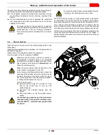
The eccentric setting should be carried out by loosening screws 7),
and turning the screw 5) to obtain the desired eccentricity.
➤
Turn clockwise, screw 5) to increase the eccentricity, increas-
ing the difference between the min. and max. capacity of the
nozzle;
➤
turn counter-clockwise, screw 5) to decrease the eccentricity
and, consequently the difference between the min. and max.
capacity of the nozzle.
When the setting is carried out, verify manually that no slow-down
occurs between 0° and 130° and that the maximum and minimum
pressures correspond to those chosen as per diagrams (Fig. 33).
If you wish to check the delivery capacity of the nozzle, open the
burner, attach the nozzle, simulate the start-up and then proceed
with observing of the maximum and minimum pressures of the fuel.
If at the maximum capacity of the nozzle (maximum pressure in the
return line) pressure fluctuations are detected on the gauge 1),
slightly decrease the pressure in the return line until they are com-
pletely eliminated.
5.4
Burner start-up
Feed electricity to the burner via the disconnecting switch on the
boiler panel.
Close the thermostats/pressure switches, set the parameters on
the RWF 40 regulator.
Please refer to the spacific manual for this operation.
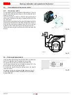
Turn the switch of Fig. 35 to position “LOCAL”.
WARNING
the proper setting of the eccentric 6) is possible
when its operation field follows the servomotor op-
eration field (20° ÷ 130°): so, that every variation of
the servomotor position corresponds to a pressure
variation.
WARNING
Do not let the piston bottom out repeatedly: the stop
ring 3)(Fig. 34) determines the max. stroke.
DANGER
Make sure that the lamps or testers connected to
the solenoids, or indicator lights on the solenoids
themselves, show that no voltage is present. If volt-
age is present, stop the burner immediately and
check the electrical wiring.
WARNING
When the burner starts, check the direction of the
motor rotation, as indicated in (Fig. 35).
As the burner is not fitted with a device to check the
sequence of the phases, the motor rotation may be
incorrect. As soon as the burner starts up, go in
front of the cooling fan of the fan motor and check it
is rotating anticlockwise. See Fig. 35.
If this is not the case:
➤
place the switch of Fig. 35 in position "0" and
wait for the control box to carry out the
switchoff phase;
➤
disconnect the electrical supply from the
burner;
➤
invert the phases on the three-phase power
supply
WARNING
For the start-up procedure and the parameters
calibration, refer to the specific instruction man-
ual of the LMV37... electronic cam supplied with
the burner.
Fig. 35
D12233
Содержание RL 70/E
Страница 2: ......
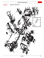
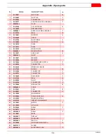
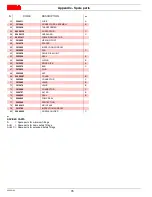
Страница 35: ...Appendix Spare parts 33 20045163 GB A Appendix Spare parts 74 75 76 80 ...

