Technical description of the burner
7
20045163
GB
3.4
Overall dimensions
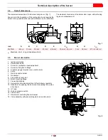
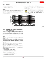
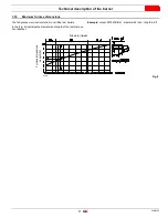
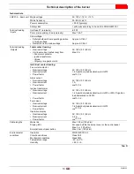
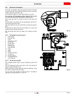
The maximum dimensions of the burners are given in (Fig. 1).
Keep in mind that inspection of the combustion head requires the
burner to be opened and the rear part withdrawn on the slide bars.
The maximum dimension of the burner when open, without casing,
is given in measurement I.
(1)
Blast tube: short - long (obtainable with kit).
3.5
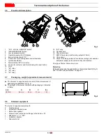
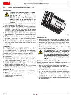
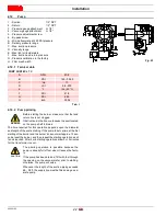
Burner description
1
Ignition electrodes
2
Combustion head
3
Screw for combustion head adjustment
4
Screw for fixing fan to flange
5
Pressure gauge for pressure on nozzle return
6
Pump
7
Non-drip nozzle holder
8
Air damper
9
Fan pressure test point
10
Boiler mounting flange
11
Flame stability disk
12
Servomotor, provides adjustment of fuel delivery regulator
13
Slide bars for opening the burner and inspecting the combu-
stion head
14
HT lead
15
High oil pressure switch
16
Fan air inlet
17
Servomotor controlling the air damper
18
Valve assembly with pressure regulator on nozzle return
Fig. 1
D1217
inch
A
B
C
D
E
F
(1)
G
H
I
(1)
RL 70/E
26
1/8”
11
21/32”
14
15/32”
21
27/32”
26
25/32”
10
23/32”
- 15
5/32”
7
7/16”
16
15/16”
37
7/16”
- 42
3/4”
1
2
3
4
15
5
6
8
9
10
11
7
16
17
13
12
18
14
Fig. 2
D11899
Содержание RL 70/E
Страница 2: ......
Страница 35: ...Appendix Spare parts 33 20045163 GB A Appendix Spare parts 74 75 76 80 ...


