Installation
5
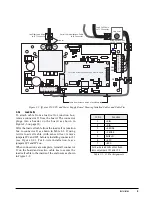
Figure 2-2. IQ plus 350 CPU and Power Supply Board, Showing Installed Cables and Cable Ties
2.3.1
Load Cells
To attach cable from a load cell or junction box,
remove connector J1 from the board. The connector
plugs into a header on the board as shown in
Figure 2-6 on page 10.
Wire the load cell cable from the load cell or junction
box to connector J1 as shown in Table 2-1. If using
6-wire load cell cable (with sense wires), remove
jumpers JP1 and JP2 before reinstalling connector J1
(see Figure 2-2). For 4-wire installation, leave
jumpers JP1 and JP2 on.
When connections are complete, reinstall connector
J1 on the board and use two cable ties to secure the
load cell cable to the inside of the enclosure as shown
in Figure 2-2.
SW1
J5
J7
JP4
J1
J4
ANALOG OUTPUT
F1
LOAD CELL CONNECTOR
SERIAL COMM & DIGITAL IN
KEYPAD CONNECTOR
F2
JP7
LOCATION OF INSTALLED ANALOG OUTPUT MODULE
Setup Switch
Serial Communications Cable
to J4 Connector
Load Cell Cable
to J1 Connector
Line Filter Load Wires
to JP7 Connector
Setup Switch Wires
to JP4 Connector
Cable tie mounts on inside of enclosure top
Cable ties
JP1
JP2
J1
4
3
2
1
7
6
5
4
3
2
1
1
2
3
4
5
6
7
J1 Pin
Function
1
+SIG
2
–SIG
3
+SENSE
4
–SENSE
5
SHIELD
6
+EXC
7
–EXC
For 6-wire load cell connections,
remove jumpers JP1 and JP2.
Table 2-1. J1 Pin Assignments
Содержание IQ plus 350
Страница 1: ...43544 IQ plus 350 Digital Weight Indicator Version 1 0 Installation Manual ...
Страница 2: ......


