RFD TX Module User Manual
www.rfdesign.com.au
20
Version 1.0 Last update 07/03/2019
6
Technical Specifications
6.1
TX Module Power Consumption
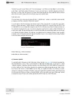
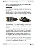
The graph indicates the current consumption of the TX Module vs the supplied battery voltage. It
should be noted that this graph is generated with the RFD modem configured for 30dBm, or 1 W,
transmission. Changing the modem power will significantly affect the current draw. The graph has
been divided to illustrate some common RC battery configurations.
Figure 21 - TX Module current consumption vs RC battery voltage.
A
)
(Blue area)
6S Ni-MH
B)
(Orange area)
3S LiFe
C)
(Red area)
3S LiPo.
6.2
Modem Specification
Table 4- Performance
Supported RF Data Rates
4, 64, 125, 250 and 500 kbits/sec
Indoor Range
500 m
–
1 km
Line-Of-Sight Range
40km or more depending on antennas
Transmit Power
0 to 30dBm in 1dBm steps
Receiver Sensitivity
>121dBm
Table 5 - Features
Configuration Method
AT Commands, APM Planner, Customized Configuration Tool
Frequency Band
902 MHz
–
928 MHz
Interference Immunity
FHSS (Frequency Hopping Spread Spectrum)
Serial Interface Data Rate
1200, 2400, 4800, 9600, 19200, 38400, 57600, 115200,
230400, 450800, 1000000 baud/s
Compliance Standards
0.2
0.4
0.6
0.8
1
1.2
6
8
10
12
14
C
u
rr
en
t
C
o
n
su
m
p
tio
n
[A
]
Battery Voltage [V]
I_Draw vs V_Bat
I(ave)
I(peak)

