background image

                      RFD TX Module User Manual 

www.rfdesign.com.au 


12 


Version 1.0                                                                                                                                                                                                              Last update 07/03/2019


-


Using a Telnet compatible serial terminal programme such as putty


1


Notes: 

1


This method is for advanced users and involves setting modem AT and RT commands via a remote terminal as such the exact method is 
not included in this document. 


When setting up the power level and the frequency band, please check the radiofrequency spectrum 
plan in your area to operate in compliance with its legislation. 

In order to avoid communication incompatibilities, it is important that both the TX Module modem 
and  the  vehicle  modem  have  the  same  firmware  version  and  it  is  v2.55  or  higher  of  the  RFD  SiK. 
Uploading the firmware onto the TX Module modem is covered in this section; how to update the 
firmware onto the vehicle modem, is covered in 

section 3.3

 and the modem datasheet in the useful 

links of section xxxx


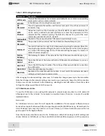
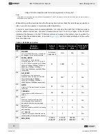
Table 3 - RFD900x parameters 

Reg 

#


S Register


Description


Default 

Value


Maximum 

Value


Minimum 

Value


Must be the same 

at both ends of 

the link?


S0


FORMAT 

This is for EEPROM version, it should not 
be changed. It is set by the firmware 

Firmware 

dependant


N/A


N/A


No


S1


SERIAL_SPEED 

Serial speed in ‘one

-

byte form’. 

Accepted values are 1, 2, 4, 9, 19, 38, 57, 
115, 230, 460 corresponding to 1200bps, 
2400bps, 4800bps, 9600bps, 19200bps, 
38400bps, 57600bps, 115200bps, 
230400bps, 460800bps and 1000000bps 
respectively. 

57


1000

3


1


No


S2


AIR_SPEED 

Air data rate in ‘one

-

byte form’. 

Accepted values are 4,64,125,250,500, 
750 corresponding to 4000bps, 
64000bps, 125000bps, 25000bps, 
500000bps and 750000bps respectively. 

64


750

3


4


Yes


S3


NETID 

Network ID. The same on both modems 
in the pair 

25


255


0


Yes


S4


TXPOWER 

Transmit power in dBm. Maximum is 
30dBm 

30


30


0


No


S5


ECC

1


Enables or disables the Golay error 
correcting code. When enabled, it 
doubles the over-the-air data usage   

0


1


0


Yes


S6


MAVLINK

2


Enables or disables the MAVLink framing 
and reporting 

1


1


0


No


S7


OP_RESEND


Opportunistic resend allows the node to 
resend packets if it has spare bandwidth 

0


1


0


No


S8


MIN_FREQ 

915000


/868000

4


927000


/869000

4


902000


/868000

4


Yes


Содержание RFD TX

Страница 1: ...www rfdesign com au RFD TX Module User s Manual RFDesign Pty Ltd 7 1 Stockwell Place Archerfield QLD 4108 rfdesign com au...

Страница 2: ...guration 5 3 2 TX Module Configuration 5 3 2 1 Configuration Webpage 6 3 2 2 WiFi Configuration 6 3 2 3 TX Module Internal RFD900x Modem settings 11 3 3 Vehicle Modem 17 4 Ground control station softw...

Страница 3: ...er compatible controllers The RFD TX Module transmits the PPM stream from the controller to the vehicle via the RF Design long range telemetry modems while also receiving telemetry data received from...

Страница 4: ...link Solid RFD modem bound to another modem 4 Button Press 5 times within 5 seconds to reset all WiFi settings to default values 5 Tabs To lock the TX Module into the radio control socket 6 RC and TX...

Страница 5: ...ky Taranis X9D Plus However it might be compatible with other transmitters To ensure compatibility check that the dimensions of the slot and the pin configuration of the connector at the back of your...

Страница 6: ...e pinout specified in Table 1 and physical dimensions described in section 2 and section 6 5 For a TARANIS X9D PLUS switch on the RC and choose the vehicle you intend to operate Navigate to the Model...

Страница 7: ...int network name i e the last 6 digits of the MAC address It should be noted that this will require the installation of some support software for correct operation for detail please see section 3 2 2...

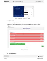
Страница 8: ...ows 8 1 B Android b First run wizard The easiest way to set up your TX Module for its initial use is with the First Run Wizard from the home page See figure 6 The wizard see figure 8 will guide you th...

Страница 9: ...or password open a web browser and enter the module s IP address by default in AP mode http 192 168 4 1 This will display the TX Module configuration To change the WiFi settings click on Edit WiFi Ne...

Страница 10: ...tion Subnet The Subnet Mask of the network that the TX Module should attempt to join as a station Host Port This is the UDP host port number This is the port that you will direct a connection to in UD...

Страница 11: ...point mode Network information such as the Subnet Mask and Gateway address can be found on a network connected device For instance in windows launch a command prompt type ipconfig and press enter Info...

Страница 12: ...data and disconnect other networking devices such as LAN cables In other cases running the Windows Network Diagnostics may help 3 2 3 TX Module Internal RFD900x Modem settings The TX Module has an RF...

Страница 13: ...tion Default Value Maximum Value Minimum Value Must be the same at both ends of the link S0 FORMAT This is for EEPROM version it should not be changed It is set by the firmware Firmware dependant N A...

Страница 14: ...put GPIO1 1 Set GPIO 1 1 as R C PPM input 0 1 0 No S17 R C output GPIO1 1 Set GPIO 1 1 as R C PPM output 0 1 0 No S185 ANT_MODE 0 Diversity 1 Antenna 1 only 2 Antenna 2 only 3 Antenna 1 TX and antenna...

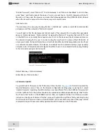
Страница 15: ...rameters available will be shown Figure 12 TX Module modem configuration page Settings can be refreshed using the Load Fresh Params button Parameters can be adjusted in the text boxes as required and...

Страница 16: ...your computer to the network with the TX Module on it Then choose Transmission Control Protocol TCP in the port field and leave the Baud field as default Press connect and fill in the pop up boxes wi...

Страница 17: ...button as per figure 13 Figure 15 Mission planner connection options As with the modem tools you will need to enter the IP address by default in AP mode 192 168 4 1 and port number in the pop up boxe...

Страница 18: ...computer yet Launch the programme and the configuration interface of figure 13 should pop up Use this interface to configure the parameters described in Table 3 RFD900x parameters When connected direc...

Страница 19: ...mputer or smart device to the configured WiFi network that is either the TX Module Access Point or the linked network when using the module as a station Then open Mission Planner on your computer or T...

Страница 20: ...and can be used however the recommended antenna for the TX Module is the 3 dBi half wave dipole which is provided in the kit and is available for purchase on the RF Design store Figure 20 900MHz Half...

Страница 21: ...C battery voltage A Blue area 6S Ni MH B Orange area 3S LiFe C Red area 3S LiPo 6 2 Modem Specification Table 4 Performance Supported RF Data Rates 4 64 125 250 and 500 kbits sec Indoor Range 500 m 1...

Страница 22: ...ty WPA WPA2 Encryption WEP TKIP AES Firmware Upgrade OTA via network Network Protocols IPv4 TCP UDP HTTP FTP User Configuration Browser interface Table 8 ESP8266 Receiver Characteristics Parameters Mi...

Страница 23: ...2 A 6 5 Physical Dimensions This section provides the TX Module dimensional drawings The module it has been designed to fit into the rear expansion bay of an FrSky Taranis X9D Plus however users may f...

Страница 24: ...re User Manual http files rfdesign com au Files documents RFD900x 20Peer to peer 20User 20Manual 20V1 1 pdf RFDesign Programming Tools Software http files rfdesign com au tools Manual http files rfdes...

Страница 25: ...RFD TX Module User Manual www rfdesign com au 24 Version 1 0 Last update 07 03 2019 8 Revision History Version Date Changes 1 Alpha 07 03 2019 Prerelease document...

Отзывы: