


Falk
™
Drive One
®
Enclosed Gear Drives
•
Owners Manual
Type D Series
•
Sizes M1130 thru M1210
(Page 9 of 27)
Rexnord Industries, LLC, 3001 W. Canal St., Milwaukee, WI 53208-4200
168-050
Telephone: 414-342-3131 Fax: 414-937-4359
January 2019
e-mail: [email protected] web: www.rexnord.com
Supersedes 04-11
(PN 2124650)
CAUTION: LUBRICANTS & INTERNAL BACKSTOPS
—
Do not use lubricants with anti-wear additives or lubricant
formulations including PTFE (Teflon), lead derivatives,
graphite or molybdenum disulfide in drives equipped with
backstops. Some lubricants in Table 8 may contain several
of these additives.
Synthetic Lubricants
Synthetic lubricants of the polyalphaolefin type are
recommended for cold climate operation, high temperature
applications, extended temperature range (all season)
operation, and/or extended lubricant change intervals. The
proper viscosity grade of synthetic lubricant is given in
Table 9. Refer to Table 10 for Synthetic lubricants.
WARNING: SYNTHETIC LUBRICANTS IN FOOD
PROCESSING INDUSTRY
— Synthetic lubricants may
contain toxic substances and should not be used in the food
processing industry without the lubricant manufacturers’
approval. Lubricants which meet USDA “H1” classification
are suitable for food processing applications.
Bearing and Seal Greases
All drives and some backstops have grease-lubricated
seals. Some vertical shaft and specially mounted drives
have grease-lubricated bearings. Drives are shipped with
NLGI #2 grease in the seal housing cavities unless otherwise
specified. Refer to Table 11 for grease recommendations.
GREASE-LUBRICATED BEARINGS
— Vertical shaft
drives with drywells have grease-lubricated lower low-
speed bearings. These bearings are lubricated at the
Factory with an NLGI#2 grease. Refer to the preventive
maintenance instructions for greasing instructions.
GREASE-LUBRICATED SEALS
— Drive One drives are
furnished with grease purged seals which minimize the
entry of contaminants into the drive. Drives are shipped
with NLGI #2 grease in the seal housing cavities unless
otherwise specified. If grease could contaminate the
product, as in the food and drug industries, it should be
removed. A grease that meets USDA “H1” classification is
suitable for food processing applications.
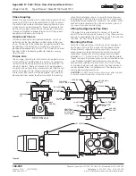
Oil Levels
TYPES DH & DB
— Fill the drive with oil to the level
indicated on the oil dipstick. Approximate oil capacities are
given on the drive nameplate.
The inspection cover is sealed with a non hardening
chemical gasket eliminator. When replacing the inspection
cover, run a bead of Loctite 515 Gasket Eliminator
«
(or equivalent) around the perimeter of the inspection
opening, making sure to circle the fastener holes.
★
Product of Henkel Corp., Rocky Hill, CT.
DRIVES WITH OIL PUMPS
— Types DV, DX, and
occasionally other types of gear drives will be equipped
with oil pumps for cooling or special lubrication
considerations. If a drive is equipped with an oil pump,
fill the drive to the level marked on the dipstick. Run the
lubrication system for several minutes to fill the system
components. Verify that the pump is circulating oil properly,
then recheck oil level. If necessary, add oil to compensate
for filter and/or cooler.
Before starting the gear drive, rotate the input shaft to
check for obstructions. Then start the drive and allow it
to run without load for several minutes. Shut down and
recheck oil level. If everything is satisfactory, the drive is
ready for operation.
Preventive Maintenance
AFTER FIRST WEEK
— Check alignment of total system
and realign where necessary. Also tighten all external
bolts and plugs where necessary. DO NOT readjust the
internal gear or bearing settings in the drive. These were
permanently set at the Factory. See Table 12 for fastener
and wrench sizes.
AFTER FIRST MONTH
— Proceed as follows:
1. Operate drive until old sump oil reaches normal
operating temperature. Shut down drive and drain
immediately.
2. Immediately flush drive with an oil of the same type
and viscosity grade as the original charge (warmed to
approximately 38°C (100°F) in cold weather) by rapidly
pouring or pumping a charge equal to 25 - 100% of the
initial fill volume or until clean oil flows through the drain.
3. Close the drain and refill the drive to the correct level
with new oil of the correct type and viscosity.
PERIODICALLY
—
1. Check the oil level of the drive when it is stopped and at
ambient temperature. Add oil if needed. If the oil level is
ABOVE the high oil level mark on the dipstick, have the
oil analyzed for water content. Moisture in the oil may
indicate that a seal or the heat exchanger is leaking. If
so, replace the defective part immediately and change
the oil. DO NOT fill above the mark indicated as leakage
or undue heating may result.
2. Check coupling alignment to make certain that
foundation settling has not caused excessive
misalignment.
3. If drive is equipped with a fan, periodically clean
accumulated foreign matter from the fan, guard, and
deflector.
4. If drive is equipped with a torque arm, check for free
movement.
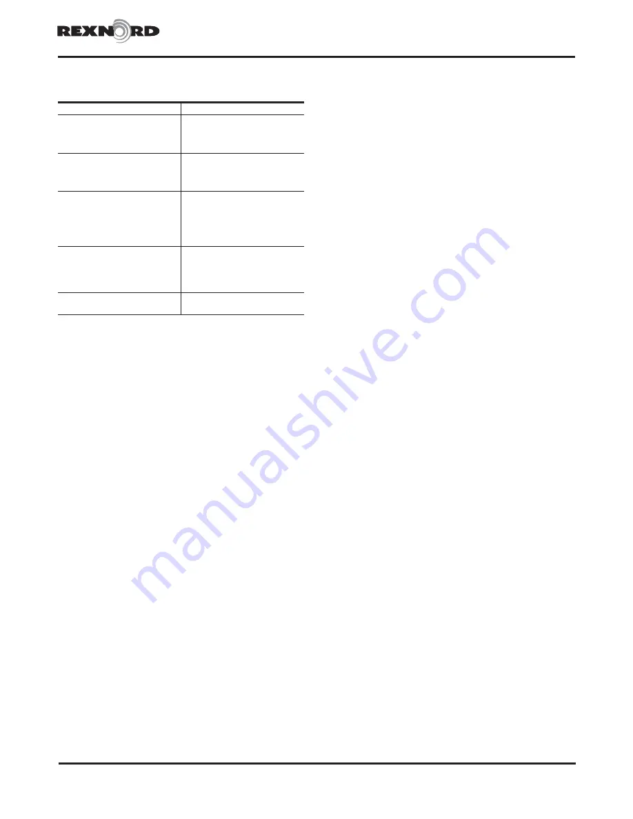
Table 11 — Greases for Bearings and Seals
–18° to +93°C (0° to 200°F)
Manufacturer
Lubricant
Amoco Oil Co.
BP Oil Co.
Chevron U.S.A., Inc.
Citgo Petroleum Corp.
Amolith Grease No. 2
Energrese LS–EP2
Industrial Grease Medium
Premium Lithium Grease No. 2
Conoco Inc.
Exxon Company, U.S.A.
E.F. Houghton & Co.
Imperial Oil Ltd.
EP Conolith Grease No. 2
Unirex N2
Cosmolube 2
Unirex N2L
Kendall Refining Co.
Keystone Div. Pennwalt Corp.
Lyondell Petrochemical (ARCO)
Mobil Oil Corp.
Mobil Oil Corp
Petro–Canada Products
Multi–Purpose Lithium Grease L421
Zeniplex 2
Litholine H EP 2 Grease
Mobilith 22
Mobilith SHC 460
«
Multipurpose EP2
Phillips 66 Co.
Shell Oil Co.
Shell Canada Limited
Sun Oil Co.
Texaco Lubricants
Philube Blue EP
Alvania Grease 2
Alvania Grease 2
Ultra Prestige EP2
Premium RB Grease
Unocal 76 (East & West)
Valvoline Oil Co.
Unoba EP2
Multilube Lithium EP Grease
★
High performance synthetic alternate.