


Falk
™
Drive One
®
Enclosed Gear Drives
•
Appendix F
Type D Series
•
Sizes M1130 thru M1210
(Page 23 of 27)
Rexnord Industries, LLC, 3001 W. Canal St., Milwaukee, WI 53208-4200
168-050
Telephone: 414-342-3131 Fax: 414-937-4359
January 2019
e-mail: [email protected] web: www.rexnord.com
Supersedes 04-11
(PN 2124650)
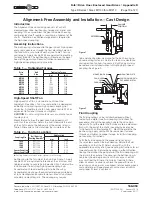
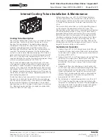
Internal Cooling Tubes Installation & Maintenance
Cooling Tube Description
The internal cooling tube accessory is a network of finned
cooling tubes. Factory-installed in the base of a drive
housing, for heat removal. The cooling tubes operate
submerged in the oil of the drive sump. The revolving
elements provide the necessary oil flow around the
cooling tubes for efficient heat transfer. No oil pumps are
required. The external requirement for the cooling tube
system is a clean water hookup supplying a flow rate of 2
gallons (8 liters) per minute at a maximum temperature of
90°F (32°C). An inlet water temperature of 70°F (21°C) is
required to obtain the system catalog thermal power rating
with a sump oil temperature of 200°F (93°C).
The number of cooling tubes required varies with drive
size, type and number of reductions. Cooling tubes are
connected in series to maintain the optimum water flow
velocity in the tubes with the specified water flow rate of 2
to 5 gallons (8 to 19 liters) per minute. Note: A typical Falk
PC cooling assembly requires between 2 to 70 gallons (8
to 265 liters) of water per minute, depending upon PC size
and cooling requirements.
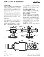
All cooling tube system connections are made outside of
the housing to eliminate the possibility of water leakage
into the drive sump. Seal rings are used at all connections
for ease of disassembly and reassembly. The standard
cooling tubes are 90/10 copper nickel alloy with aluminum
fins. Cooling tube connections are cadmium-plated mild
steel with “Buna-N” seal rings.
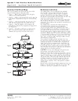
Water connections are .500”-14 NPT fittings located at
the high-speed end. The water outlet is located on the
high-speed end of the drive. The water inlet connection is
a straight fitting located on the lowest cooling tube in the
drive.
The water outlet connection is a right angle fitting (faced
up) located on the uppermost tube in the drive. The
cooling tube system connections are selected and located
so that the cooling system is always full of water during
operation for maximum heat transfer. The water inlet and
outlet connections may be moved to the opposite end of
the drive by removing the water inlet, outlet and all “loop
end” fitting assemblies and by reinstalling them on the
same tubes at the opposite end of the drive. Refer to the
Maintenance Instructions on page 24 and Figures 7 & 8 on
page 25 for disassembly and reassembly.
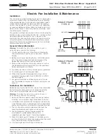
Installation & Operation
1. Connect the .500”-14 NPT straight water inlet fitting to
a source of clean, fresh water. Water must be regulated
to a minimum of 2 gallons (8 liters) per minute and must
not exceed 90°F (32°C).
2. Connect the .500”-14 NPT right angle water outlet fitting
(faced up) to an open drain. Do not pressurize the
cooling tube system. The turned up water outlet fitting
ensures that the system is always full of water during
operation.
3. Control water flow rate to between 2 and 5 gallons (8
and 19 liters) per minute to minimize fouling at low flow
rates or tube erosion at high flow rates. The water flow
rate may be reduced to 1 gallon (4 liters) per minute
if clean, fresh (drinking quality) water is used and the
sump oil temperature can be maintained within the
maximum limit of 200°F (93°C).
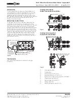
4. For shutdowns at ambient temperatures less than 32°F
(0°C), drain the cooling tube system by removing the
“loop end” assemblies on the end of the drive opposite
the water inlet. Refer to Figure 8 on page 25 for typical
assemblies and record location of assemblies for
reinstallation purposes.