Rexnord Falk Drive One DB Скачать руководство пользователя страница 7

Falk

 Drive One

®

 Enclosed Gear Drives 

 Owners Manual

Type D Series 

 Sizes M1130 thru M1210 

(Page 7 of 27)

Rexnord Industries, LLC, 3001 W. Canal St., Milwaukee, WI 53208-4200 

168-050

Telephone: 414-342-3131 Fax: 414-937-4359 

 January 2019

e-mail: [email protected] web: www.rexnord.com 

Supersedes 04-11

(PN 2124650)

Lubrication Recommendations

Carefully follow lubrication instructions on the gear 

drive nameplate, warning tags, and installation manuals 

furnished with the gear drive.
Lubricants listed in this manual are typical ONLY and 

should not be construed as exclusive recommendations. 

Industrial type petroleum based rust and oxidation 

inhibited (R & O) gear lubricants or industrial type sulfur-

phosphorus extreme pressure (EP) gear lubricants are the 

recommended lubricants for ambient temperatures of  -9°C 

to +50°C (15°F to 125°F).
For drives operating outside the above temperature range, 

refer to “Synthetic Lubricants” paragraphs. Synthetic 

lubricants can also be used in normal climates.

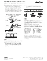
Table 5 — Oil Pump Electrical Specifications

Drive Size

M1130 Thru M1210

Power

1.12 kw

1.5 hp

Cycles, Hz

50

60

RPM

1425

1750

Voltage

220/380/440

208/230/460

Table 6 — Viscosity Grade 

Recommendations for Petroleum – 

Based R & O or EP Lubricants

Output RPM

Normal Climates

-9° to +16°C 

(15° to 60°F)

10° to 52°C 

(50° to 125°F)

ISO-VG

AGMA

ISO-VG

AGMA

Output RPM Below 80

150

4

320

6

Output RPM 80 & Above

150

4

220

5

Table 7 — Petroleum Based R & O Gear Oils 


Maximum operating temperature of  lubricants 93°C (200°F)

AGMA Viscosity Grade

4

5

6

7

ISO Viscosity Grade

150

220

320

460

Viscosity SSU @ 100°F

626-765

918-1122

1335-1632

1919-2346

Viscosity cSt @ 40°C

135-165

198-242

288-352

414-506

Manufacturer

Lubricant

Lubricant

Lubricant

Lubricant

Amoco Oil Co. 

BP Oil Co. 

Chevron U.S.A., Inc. 

Citgo Petroleum Corp.

Amer.Ind. Oil 150 

. . . . .  

Machine Oil AW 150 

Citgo Pacemaker 150

Amer.Ind. Oil 220 

Energol HLP-HD 220 

Machine Oil AW 220 

Citgo Pacemaker 220

Amer. Ind. Oil 320 

. . . . . 

Machine Oil AW 320 

Citgo Pacemaker 320

Amer. Ind. Oil 460 

. . . . . 

. . . . . 

Citgo Pacemaker 460

Conoco Inc. 

Exxon Company, U.S.A. 

Houghton International, Inc. 

Imperial Oil Ltd.

Dectol R&O Oil 150 

Teresstic 150 

Hydro–Drive HP 750 

Teresso 150

Dectol R&O Oil 220 

Teresstic 220 

Hydro–Drive HP 1000 

Teresso 220

Dectol R&O Oil  320 

Teresstic 320 

 . . . . . 

Teresso 320

Dectol R&O Oil 460 

Teresstic 460 

. . . . . 

. . . . .

Kendall Refining Co. 

Keystone Lubricants 

Lyondell Petrochemical (ARCO) 

Mobil Oil Corp. 

Pennzoil Products company 

Petro–Canada Products

Four Seasons AW 150 

KLC–40 

Duro 150 

DTE Oil Extra Heavy 

Pennzbell AW Oil 150 

Premium R & O 150

. . . . . 

KLC-50 

Duro 220 

DTE Oil BB 

Pennzbell AW Oil 220 

Premium R & O 220

. . . . . . 

. . . . . 

Duro 32 

DTE Oil AA 

Pennzbell AW Oil 320 

Premium R & O 320

. . . . . 

. . . . . 

. . . . . 

DTE Oil HH 

Pennzbell AW Oil 460 

. . . . .

Phillips 66 Co. 

Shell Oil Co. 

Shell Canada Limited 

Sun Oil Co. 

Texaco Lubricants

Magnus Oil 150 

Morlina 150 

Tellus 150 

Sunvis 9150 

Regal Oil R&O 150

Magnus Oil 220 

Morlina 220 

Tellus 220 

Sunvis 9220 

Regal Oil R&O 220

Magnus Oil 320 

Morlina 320 

Tellus 320 

. . . . . 

Regal Oil R&O 320

. . . . . 

Morlina 460 

. . . . . 

. . . . . 

Regal Oil R&O 460

Unocal 76 (East) 

Unocal 76 (West) 

Valvoline Oil Co

Unax RX 150 

Turbine Oil 150 

Valvoline AW ISO 150

Unax RX 220 

Turbine Oil 220 

Valvoline AW ISO 220

Unax AW 320 

Turbine Oil 320 

Valvoline AW ISO 320

Turbine Oil 460 

Turbine Oil 460 

. . . . . 


† Minimum viscosity index of  90.

Table 8 — Extreme Pressure Lubricants 


(Maximum Operating Temperature 
93°C(200°F)

Manufacturer

Lubricant

Amoco Oil Co. 

BP Oil Co. 

Chevron U.S.A. Inc. 

Citgo Petroleum Corp.

Permagear/Amogear EP 

Energear EP 

Gear Compounds EP 

Citgo EP Compound

Conoco Inc. 

Exxon Co. U.S.A. 

E.F. Houghton & Co. 

Imperial Oil Ltd.

Gear Oil  

Spartan EP 

MP Gear Oil  

Spartan EP

Kendall Refining Co. 

Keystone Div. Pennwalt Corp. 

Lyondell Petrochemical (ARCO) 

Mobil Oil Corp. 

Petro–Canada Products

Kendall NS-MP 

Keygear 

Pennant NL 

Mobilgear 

Ultima EP

Phillips 66 Co. 

Shell Oil Co. 

Shell Canada Limited 

Sun Oil Co. 

Texaco Lubricants

Philgear 

Omala Oil 

Omala Oil 

Sunep 

Meropa

Valvoline Oil Co.

AGMA EP


† Minimum viscosity index of  90.

VISCOSITY (IMPORTANT)

 — The proper grade for R & 

O and EP lubricants is found in Table 7. For cold climate 

conditions refer to Table 9, page 8 and the “Synthetic 

Lubricant” paragraphs.
If a gear drive operates in a typical indoor environment 

where the ambient temperature is within 21°C to 52°C (70°F 

to 125°F), the oil viscosity could be increased one AGMA 

grade above that shown for the 10°C to 52°C (50°F to 125°F) 

range. That is, an AGMA Number 6 or 7 could be substituted 

for a 5 or 6 respectively, under these ambient conditions.

Содержание Falk Drive One DB

Страница 1: ...s LLC the Company warrants that Drive One gear drives I conform to Company s published specifications and II are free from defects of material for three years from the date of shipment Company does not warrant any non Company branded products or components manufacturer s warranty applies or any defects in damage to or failure of products caused by I dynamic vibrations imposed by the drive system i...

Страница 2: ...ately aligned at the Factory with the bedplate mounted on a large flat assembly plate Shim under the bedplate foot pads until the gear drive is level and all feet are in the same plane Check high speed shaft coupling alignment If the coupling is misaligned the bedplate is shimmed incorrectly Re shim bedplate and recheck high speed coupling alignment If necessary realign motor Shaft Mounted Drives ...

Страница 3: ...0 110 0 0 0 140 129 334 129 784 109 860 110 000 M1160 135 0 0 0 160 146 674 147 264 134 840 135 000 130 0 0 0 160 144 314 144 784 129 840 130 000 125 0 0 0 160 141 814 142 284 124 840 125 000 120 0 0 0 160 139 334 139 784 119 860 120 000 M1170 150 0 0 0 160 164 193 164 773 149 840 150 000 140 0 0 0 160 159 193 159 773 139 840 140 000 130 0 0 0 160 154 293 154 773 129 840 130 000 M1180 170 0 0 0 16...

Страница 4: ...distance from the nut DO NOT apply ANTI SEIZE on these areas high speed shaft by dividing the tightening torque indicated in Table 3 by the drive s ratio Torque Ratio Apply the calculated torque to the high speed shaft or coupling using a spanner chain or pipe wrench Be careful not to damage the usable length of the high speed shaft Remove the fixed wrench from the TA bushing nut and reassemble th...

Страница 5: ... ring and thrust plate from the hollow shaft 3 Select the backing bolts from the table above and install them into the three threaded holes in the end of the driven shaft The head of the backing bolts provides a working surface for the removal bolts 4 Re insert the thrust plate and retaining ring into the hollow shaft and select the removal bolts from the table above 5 Thread three removal bolts i...

Страница 6: ...gnment and assembly of coupling Steelflex Illustrated RIGHT WRONG LEVEL GEAR DRIVE WALL SQUARE AND PARALLEL Fastener Tightening Torques Use the tightening torque values specified in Table 4 for fastening Falk gear drives motors and accessories to their mounting surfaces with un lubricated fasteners DO NOT use these values for torque locking fasteners or for fastening components with aluminum feet ...

Страница 7: ... HP 750 Teresso 150 Dectol R O Oil 220 Teresstic 220 Hydro Drive HP 1000 Teresso 220 Dectol R O Oil 320 Teresstic 320 Teresso 320 Dectol R O Oil 460 Teresstic 460 Kendall Refining Co Keystone Lubricants Lyondell Petrochemical ARCO Mobil Oil Corp Pennzoil Products company Petro Canada Products Four Seasons AW 150 KLC 40 Duro 150 DTE Oil Extra Heavy Pennzbell AW Oil 150 Premium R O 150 KLC 50 Duro 2...

Страница 8: ... AGMA Viscosity Grade 0S 2S 4S 5S 6S 7S ISO Viscosity Grade 32 68 150 220 320 460 Viscosity cSt 40 C 28 8 35 2 61 2 74 8 135 165 198 242 288 352 414 506 Viscosity SSU 100 F 134 164 284 347 626 765 918 1122 1335 1632 1919 2346 Manufacturer Lubricant Chevron U S A Inc Clarity Synthetic PM Oil 220 Syn Gear Lube Tegra 150 Syn Gear Lube Tegra 220 Syn Gear Lube Tegra 320 Syn Gear Lube Tegra 460 Conoco I...

Страница 9: ...iderations If a drive is equipped with an oil pump fill the drive to the level marked on the dipstick Run the lubrication system for several minutes to fill the system components Verify that the pump is circulating oil properly then recheck oil level If necessary add oil to compensate for filter and or cooler Before starting the gear drive rotate the input shaft to check for obstructions Then star...

Страница 10: ... the food processing industry A grease that meets the USDA H1 classification is suitable for food processing applications CAUTION Rapid greasing with a power grease gun can force grease inward past the seals causing seal leaks GREASE LUBRICATED BEARINGS TYPES DV AND DX Most vertical low speed shaft drives have a grease lubricated lower low speed bearing Grease bearings during oil changes or at int...

Страница 11: ...torstor quantities Rotate the shafts several times by hand Before operating drives which have been stored or inactive must be filled to the proper level with oil meeting the specifications given in this manual Refer to Manual 128 014 for Start up after Storage instructions Periodically inspect stored or inactive gear drives and spray or add rust inhibitor every six months or more often if necessar...

Страница 12: ...ype D Series Sizes M1130 thru M1210 168 050 Rexnord Industries LLC 3001 W Canal St Milwaukee WI 53208 4200 January 2019 Telephone 414 342 3131 Fax 414 937 4359 Supersedes 04 11 e mail info rexnord com web www rexnord com PN 2124650 THIS PAGE INTENTIONALLY LEFT BLANK ...

Страница 13: ...racket should be added to the structure after the drive has been secured to the driven equipment NOTE Do not fasten the torque to the support structure at this time 2 Secure the drive to the driven equipment via the TA bushing or rigid coupling connection 3 Check that the torque arm remains perpendicular and centered in the clevis if mounted If the torque arm is not perpendicular and centered repo...

Страница 14: ...to the driven equipment NOTE Do not fasten the torque arm to the support structure at this time 2 Secure the drive to the driven equipment via the TA Bushing shrink disc or rigid coupling connection 3 Mount the anchor bracket or clevis to the drive or drive system if not already done Locate the position of the anchor bracket to be mounted to the support structure Match drill the mounting holes for...

Страница 15: ...IN ROD END MALE ROD END FEMALE TORQUE ARM PIN MOUNTING HARDWARE SUPPLIED BY CUSTOMER Figure 1 ANCHOR BRACKET RETAINING RING SPACER ROD END ROD END SPACER RETAINING RING ANCHOR BRACKET MOUNTING HARDWARE PROVIDED TORQUE ARM PIN JAM NUT TURNBUCKLE JAM NUT TORQUE ARM PIN MOUNTING HARDWARE SUPPLIED BY CUSTOMER Figure 3 CROWNED TORQUE ARM PIN CLEVIS ROD END ANCHOR BRACKET RETAINING RING JAM NUT TORQUE A...

Страница 16: ...g screw holes are provided in gear drive housing to aid in fixing the shims Begin at the low speed shaft end and level across the length and then the width of the gear drive Use a feeler gauge to ensure that all pads are supported Bolt down the drive to the torque specified in Table 4 page 6 Mounting Motor and Coupling Alignment Shims are provided for motor mounting Holes must be drilled into the ...

Страница 17: ...nstall the fluid coupling on the high speed shaft of the gear drive per fluid coupling instructions If a shaft fan is required remove every other of the twelve delay fill chamber fasteners Install the fan adapter ring to the fluid coupling using the long socket head cap screws provided Place a mounting post between the delay fill chamber flange and the adapter ring as shown in Figure 1 After all f...

Страница 18: ...te on the bell housing before installing the coupling Once the motor is secured measure the distance D between the end of the motor shaft and the high speed shaft of the drive See Figure 4 Subtract the distance D from the length of the spacer coupling BE Then divide this value in half to find the overhang of each hub Overhang BE D 2 The overhang will be negative This is the amount each hub overhan...

Страница 19: ...N Do not over tighten fasteners into plastic fan as fan may crack Mount the fan hub on the gear drive high speed shaft such that the set screw hole in the hub is towards the end of the shaft Locate the hub axially at the values listed in Table 2 Dimensions listed are from the inside face of the bell housing to the far side of the hub See Figure 1 Apply Loctite 242 or equivalent to threads of the s...

Страница 20: ...ate Carriage may be adjusted from center to either far end of the housing to facilitate installation of pin Ensure that adjusting rod locking plate is NOT installed at this time as it will prevent adjustment of the torque arm assembly Assemble anchor bracket to male rod end with a spacer on each side and secure with pin and retaining ring Lifting the Alignment Free Drive Lifting points are provide...

Страница 21: ...s the National Electrical Code NEC and Occupational Safety and Health Act OSHA 4 Fan motor must be securely and adequately grounded 5 All working parts should be grounded 6 When cleaning electrical equipment always use an approved cleaning agent See CLEANING in NOTES section page 22 7 For general ventilation and cooling use only Do not use if hazardous or explosive materials and vapors are present...

Страница 22: ...2 POSITION A POSITION B POSITION C 1 1 2 Mounting Positions For Position A B Remove Plug 1 For Position C Remove Plug 2 Note Never use copper or brass fastening materials Figure 3 8 Connect power to the motor using an approved wiring method See Figure 1 for connection diagrams 9 Before starting the fan double check to ensure there are no obstructions that could interfere with proper fan operation ...

Страница 23: ... cadmium plated mild steel with Buna N seal rings Water connections are 500 14 NPT fittings located at the high speed end The water outlet is located on the high speed end of the drive The water inlet connection is a straight fitting located on the lowest cooling tube in the drive The water outlet connection is a right angle fitting faced up located on the uppermost tube in the drive The cooling t...

Страница 24: ...d by flushing with commercially available cleaning compounds such as Oakite or Dowell The commercially available cleaning compounds are corrosive and must be used in accordance with their manufacturer s recommendations Cleaning may also be accomplished by means of a rod or wire brush Remove the tube end seal ring fittings Figures 7 8 on page 25 and pass a 500 12 mm diameter rod or wire brush throu...

Страница 25: ... installed in series with a ball valve to limit maximum water flow Refer to Figure 6 for recommended plumbing diagram The water flow control valve will control water flow rates to less than 2 gallons 8 liters per minute however the cooling tubes will be subject to increased fouling and may require cleaning at more frequent intervals WATER SUPPLY 2 GPM MIN 8 LITERS PER MIN 90 F 32 C MAX TEMP WATER ...

Страница 26: ... 00 M20 x 2 5 x 40 750 10 x 1 50 M24 x 3 x 70 M24 x 3 x 70 341 13 43 284 11 18 M1140 M24 x 3 x 90 1 000 8UNC x 3 50 M24 x 3 x 45 1 00 8 x 2 00 M30 x 3 5 x 80 M30 x 3 5 x 80 386 15 20 319 12 55 M1150 M24 x 3 x 90 1 000 8UNC x 3 50 M24 x 3 x 45 1 00 8 x 2 00 M30 x 3 5 x 80 M30 x 3 5 x 80 406 15 98 334 13 15 M1160 M24 x 3 x 90 1 000 8UNC x 3 50 M24 x 3 x 45 1 00 8 x 2 00 M30 x 3 5 x 80 M30 x 3 5 x 80...

Страница 27: ...G 1 EACH END SEALED WITH LOCTITE PIPE JOINT COMPOUND 30557 P N D004945 1B SQUARE HEAD MAGNETIC DRAIN PLUG 1 EACH END SEALED WITH LOCTITE PIPE JOINT COMJPOUND 30557 P N D004945 5B INSPECTION COVER IF COVER WAS REMOVED APPLY A CONTINOUOUS BEAD OF LOCTITE 515 GASKET ELIMINATOR P N 99409561 OR EQUIVALENT TO HOUSING INSPECTION COVER BOLTING SURFACE MAKE SURE THAT THE BEAD IS LOCATED INSIDE THE BOLT PAT...

Отзывы: