Rexnord Falk Drive One DB Скачать руководство пользователя страница 5

Falk

 Drive One

®

 Enclosed Gear Drives 

 Owners Manual

Type D Series 

 Sizes M1130 thru M1210 

(Page 5 of 27)

Rexnord Industries, LLC, 3001 W. Canal St., Milwaukee, WI 53208-4200 

168-050

Telephone: 414-342-3131 Fax: 414-937-4359 

 January 2019

e-mail: [email protected] web: www.rexnord.com 

Supersedes 04-11

(PN 2124650)

thrust plate retaining ring and thrust plate, install backing 

bolt, and reinstall thrust plate with retaining ring. Remove 

bushing nut retaining ring. Install removal bolt in thrust 

plate and tighten against backing bolt to release drive 

from driven shaft (insert screwdriver in thrust plate key 

slot to engage hollow shaft keyway to prevent thrust plate 

rotation while tightening removal bolt).

7.  Prepare drive for lifting by disconnecting the torque arm.
8.  Slide the drive from the bushing. The bushing can be 

left in place or removed as required. If  bushing will not 

slide off  the shaft, insert a small prybar into the split of  

the bushing and pry the split open slightly to loosen the 

bushing and remove from the shaft.

Bushing 

Size

Removal Bolt Size & 

Minimum Length

Max Tightening 

Torque 

Nm (lb-ft)

Backing Bolt Size 

& Max Length

190-200 mm

M30 x 3.5 x 200 mm

1355 (1000)

M24 x 3 x 45 mm

7.50-8.00 inch 1.500-6UNC x 7.50 inch

1125 (830)

1.250-7UNC x 3.00 inch

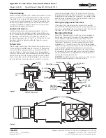
Taper Bushing – Sizes M1200 & M1210

Driven shafts are retained on M1200 & M1210 drives with 

a thrust plate and three cap screw arrangement. With 

the driven shaft keyway at the 12 o’clock position, slide 

bushing onto the driven shaft, flange end first, and position 

the keyway slot over the shaft keyway. The bushing may 

have to be opened slightly to assist in installation. Insert a 

screwdriver into the slot in the bushing and very lightly pry 

open until the bushing slides onto the shaft. Insert the drive 

key furnished with the bushing into the shaft keyway.

Installation of Shaft-Mounted Drives 

Sizes M1200 M1210

1.  Before lifting the drive into position, rotate the high-

speed shaft until the hollow shaft keyway will be in 

position to line-up with the driven shaft key.

2.  Lift the drive into position and slide onto the drive shaft 

taking care that the driven shaft key seats into the hollow 

shaft keyway. DO NOT hammer or use excessive force.

3.  Align three holes in hollow shaft thrust plate with tapped 

holes in end of  driven shaft. Insert fasteners  through 

thrust plate and engage tapped holes in driven shaft 

one to two turns by hand to ensure that fasteners are 

not cross-threaded.

4.  Tighten fasteners to the torque vales (± 10%) listed below:

M24 x 3 – 640 Nm (470 lb-ft) for metric-based bushing 

bores.
1.250-7UNC – 1400 Nm (1060 lb-ft) for inch-based 

bushing bores.

5.  Re-install low-speed shaft cover.

Removal of Shaft-Mounted Drives 

Sizes M1200 & M1210

1.  Remove low-speed shaft cover.
2.  Remove three thrust plate fasteners, retaining ring and 

thrust plate from the hollow shaft.

3.  Select the backing bolts from the table above and install 

them into the three threaded holes in the end of  the 

driven shaft. The head of  the backing bolts provides a 

working surface for the removal bolts.

4.  Re-insert the thrust plate and retaining ring into the hollow 

shaft and select the removal bolts from the table above.

5.  Thread three removal bolts into the thrust plate until they 

contact the backing bolt heads.

6.  Tighten the removal bolts equally in stages to the torque 

indicated in the table above. After torquing the bolts, as 

instructed, strike the bolts sharpy with a hammer and re-

torque the bolts if separation of the drive from the driven 

shaft did not occur. Repeat this procedure, re-torquing 

the bolts after each blow, until separation occurs.

7.  Prepare drive for lifting by disconnecting the torque arm.
8.  Slide the drive from the bushing. The bushing can be 

left in place or removed as required. If  bushing will not 

slide off  the shaft, insert a small prybar into the split of  

the bushing and pry the split open slightly to loosen the 

bushing and remove from the shaft.

Shaft Connections

WARNING

: Provide suitable guards in accordance with 

local and national standards.

COUPLING CONNECTIONS

 — The performance and 

life of  any coupling depends largely upon how well the 

coupling is installed and serviced. Refer to the coupling 

manufacturer’s manual for specific instructions.
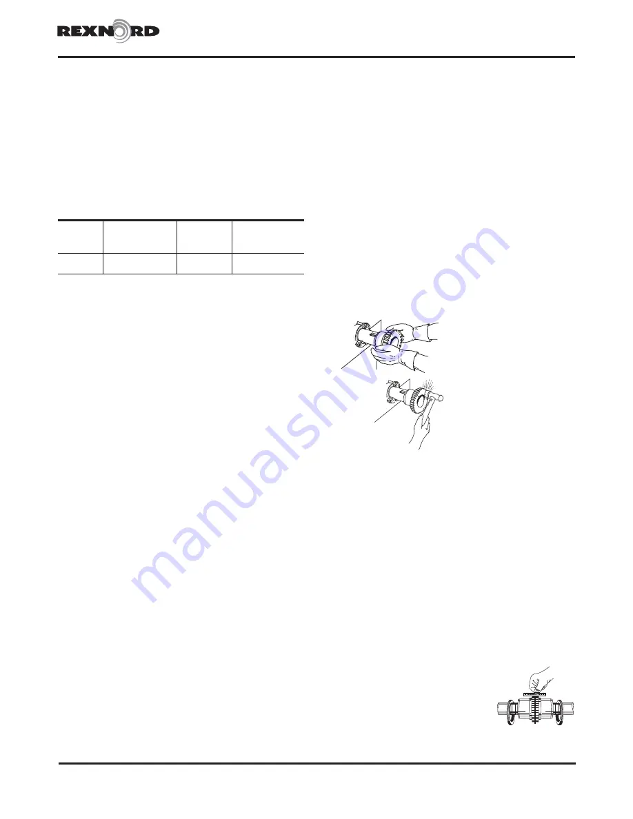
CORRECT METHOD

Heat interference-fitted  hubs, 

pinions, sprockets or pulleys to 

a maximum of  135°C (275°F) 

and slide onto gear drive shaft.

INCORRECT METHOD

DO NOT drive coupling hub, 

pinion, sprocket or pulley onto 

the shaft. An endwise blow 

on the shaft/coupling may 

damage gears and bearings.

FALK COUPLINGS

 — (Except fluid type) Detailed 

installation manuals are available from the Factory, your 

local Rexnord representative or distributor — just provide 

size and type designations stamped on the coupling. 

For lubricant requirements and a list of  typical lubricants 

meeting Rexnord specifications, refer to appropriate 

coupling service manual.

FALK FLANGED TYPE RIGID COUPLINGS

 — These are 

typically used on drives with vertical output shafts. The 

low-speed shaft extension ends of  the solid vertical shaft 

drives are drilled and tapped to accommodate coupling 

keeper plates. Tightening torques for fastener, including 

keeper plate fasteners are listed in Table 4, page 6.

FALK FLUID COUPLINGS

 — Refer to the installation 

manual furnished with the Falk fluid coupling for installation 

and startup instructions. For Alignment-Free drives, refer to 

Appendix D.

GAP AND ANGULAR ALIGNMENT

 — If  possible, after 

mounting coupling hubs, position the driving and driven 

equipment so that the distance 

between shaft ends is equal to the 

coupling gap. Align the shafts by 

placing a spacer block, equal in 

thickness to required gap, between 

hub faces, as shown at right, and 

also at 90° intervals around the hub. 

Check with feelers.

– CAUTION – 

DO NOT HAMMER

Steelflex

®

 Illustrated

Содержание Falk Drive One DB

Страница 1: ...s LLC the Company warrants that Drive One gear drives I conform to Company s published specifications and II are free from defects of material for three years from the date of shipment Company does not warrant any non Company branded products or components manufacturer s warranty applies or any defects in damage to or failure of products caused by I dynamic vibrations imposed by the drive system i...

Страница 2: ...ately aligned at the Factory with the bedplate mounted on a large flat assembly plate Shim under the bedplate foot pads until the gear drive is level and all feet are in the same plane Check high speed shaft coupling alignment If the coupling is misaligned the bedplate is shimmed incorrectly Re shim bedplate and recheck high speed coupling alignment If necessary realign motor Shaft Mounted Drives ...

Страница 3: ...0 110 0 0 0 140 129 334 129 784 109 860 110 000 M1160 135 0 0 0 160 146 674 147 264 134 840 135 000 130 0 0 0 160 144 314 144 784 129 840 130 000 125 0 0 0 160 141 814 142 284 124 840 125 000 120 0 0 0 160 139 334 139 784 119 860 120 000 M1170 150 0 0 0 160 164 193 164 773 149 840 150 000 140 0 0 0 160 159 193 159 773 139 840 140 000 130 0 0 0 160 154 293 154 773 129 840 130 000 M1180 170 0 0 0 16...

Страница 4: ...distance from the nut DO NOT apply ANTI SEIZE on these areas high speed shaft by dividing the tightening torque indicated in Table 3 by the drive s ratio Torque Ratio Apply the calculated torque to the high speed shaft or coupling using a spanner chain or pipe wrench Be careful not to damage the usable length of the high speed shaft Remove the fixed wrench from the TA bushing nut and reassemble th...

Страница 5: ... ring and thrust plate from the hollow shaft 3 Select the backing bolts from the table above and install them into the three threaded holes in the end of the driven shaft The head of the backing bolts provides a working surface for the removal bolts 4 Re insert the thrust plate and retaining ring into the hollow shaft and select the removal bolts from the table above 5 Thread three removal bolts i...

Страница 6: ...gnment and assembly of coupling Steelflex Illustrated RIGHT WRONG LEVEL GEAR DRIVE WALL SQUARE AND PARALLEL Fastener Tightening Torques Use the tightening torque values specified in Table 4 for fastening Falk gear drives motors and accessories to their mounting surfaces with un lubricated fasteners DO NOT use these values for torque locking fasteners or for fastening components with aluminum feet ...

Страница 7: ... HP 750 Teresso 150 Dectol R O Oil 220 Teresstic 220 Hydro Drive HP 1000 Teresso 220 Dectol R O Oil 320 Teresstic 320 Teresso 320 Dectol R O Oil 460 Teresstic 460 Kendall Refining Co Keystone Lubricants Lyondell Petrochemical ARCO Mobil Oil Corp Pennzoil Products company Petro Canada Products Four Seasons AW 150 KLC 40 Duro 150 DTE Oil Extra Heavy Pennzbell AW Oil 150 Premium R O 150 KLC 50 Duro 2...

Страница 8: ... AGMA Viscosity Grade 0S 2S 4S 5S 6S 7S ISO Viscosity Grade 32 68 150 220 320 460 Viscosity cSt 40 C 28 8 35 2 61 2 74 8 135 165 198 242 288 352 414 506 Viscosity SSU 100 F 134 164 284 347 626 765 918 1122 1335 1632 1919 2346 Manufacturer Lubricant Chevron U S A Inc Clarity Synthetic PM Oil 220 Syn Gear Lube Tegra 150 Syn Gear Lube Tegra 220 Syn Gear Lube Tegra 320 Syn Gear Lube Tegra 460 Conoco I...

Страница 9: ...iderations If a drive is equipped with an oil pump fill the drive to the level marked on the dipstick Run the lubrication system for several minutes to fill the system components Verify that the pump is circulating oil properly then recheck oil level If necessary add oil to compensate for filter and or cooler Before starting the gear drive rotate the input shaft to check for obstructions Then star...

Страница 10: ... the food processing industry A grease that meets the USDA H1 classification is suitable for food processing applications CAUTION Rapid greasing with a power grease gun can force grease inward past the seals causing seal leaks GREASE LUBRICATED BEARINGS TYPES DV AND DX Most vertical low speed shaft drives have a grease lubricated lower low speed bearing Grease bearings during oil changes or at int...

Страница 11: ...torstor quantities Rotate the shafts several times by hand Before operating drives which have been stored or inactive must be filled to the proper level with oil meeting the specifications given in this manual Refer to Manual 128 014 for Start up after Storage instructions Periodically inspect stored or inactive gear drives and spray or add rust inhibitor every six months or more often if necessar...

Страница 12: ...ype D Series Sizes M1130 thru M1210 168 050 Rexnord Industries LLC 3001 W Canal St Milwaukee WI 53208 4200 January 2019 Telephone 414 342 3131 Fax 414 937 4359 Supersedes 04 11 e mail info rexnord com web www rexnord com PN 2124650 THIS PAGE INTENTIONALLY LEFT BLANK ...

Страница 13: ...racket should be added to the structure after the drive has been secured to the driven equipment NOTE Do not fasten the torque to the support structure at this time 2 Secure the drive to the driven equipment via the TA bushing or rigid coupling connection 3 Check that the torque arm remains perpendicular and centered in the clevis if mounted If the torque arm is not perpendicular and centered repo...

Страница 14: ...to the driven equipment NOTE Do not fasten the torque arm to the support structure at this time 2 Secure the drive to the driven equipment via the TA Bushing shrink disc or rigid coupling connection 3 Mount the anchor bracket or clevis to the drive or drive system if not already done Locate the position of the anchor bracket to be mounted to the support structure Match drill the mounting holes for...

Страница 15: ...IN ROD END MALE ROD END FEMALE TORQUE ARM PIN MOUNTING HARDWARE SUPPLIED BY CUSTOMER Figure 1 ANCHOR BRACKET RETAINING RING SPACER ROD END ROD END SPACER RETAINING RING ANCHOR BRACKET MOUNTING HARDWARE PROVIDED TORQUE ARM PIN JAM NUT TURNBUCKLE JAM NUT TORQUE ARM PIN MOUNTING HARDWARE SUPPLIED BY CUSTOMER Figure 3 CROWNED TORQUE ARM PIN CLEVIS ROD END ANCHOR BRACKET RETAINING RING JAM NUT TORQUE A...

Страница 16: ...g screw holes are provided in gear drive housing to aid in fixing the shims Begin at the low speed shaft end and level across the length and then the width of the gear drive Use a feeler gauge to ensure that all pads are supported Bolt down the drive to the torque specified in Table 4 page 6 Mounting Motor and Coupling Alignment Shims are provided for motor mounting Holes must be drilled into the ...

Страница 17: ...nstall the fluid coupling on the high speed shaft of the gear drive per fluid coupling instructions If a shaft fan is required remove every other of the twelve delay fill chamber fasteners Install the fan adapter ring to the fluid coupling using the long socket head cap screws provided Place a mounting post between the delay fill chamber flange and the adapter ring as shown in Figure 1 After all f...

Страница 18: ...te on the bell housing before installing the coupling Once the motor is secured measure the distance D between the end of the motor shaft and the high speed shaft of the drive See Figure 4 Subtract the distance D from the length of the spacer coupling BE Then divide this value in half to find the overhang of each hub Overhang BE D 2 The overhang will be negative This is the amount each hub overhan...

Страница 19: ...N Do not over tighten fasteners into plastic fan as fan may crack Mount the fan hub on the gear drive high speed shaft such that the set screw hole in the hub is towards the end of the shaft Locate the hub axially at the values listed in Table 2 Dimensions listed are from the inside face of the bell housing to the far side of the hub See Figure 1 Apply Loctite 242 or equivalent to threads of the s...

Страница 20: ...ate Carriage may be adjusted from center to either far end of the housing to facilitate installation of pin Ensure that adjusting rod locking plate is NOT installed at this time as it will prevent adjustment of the torque arm assembly Assemble anchor bracket to male rod end with a spacer on each side and secure with pin and retaining ring Lifting the Alignment Free Drive Lifting points are provide...

Страница 21: ...s the National Electrical Code NEC and Occupational Safety and Health Act OSHA 4 Fan motor must be securely and adequately grounded 5 All working parts should be grounded 6 When cleaning electrical equipment always use an approved cleaning agent See CLEANING in NOTES section page 22 7 For general ventilation and cooling use only Do not use if hazardous or explosive materials and vapors are present...

Страница 22: ...2 POSITION A POSITION B POSITION C 1 1 2 Mounting Positions For Position A B Remove Plug 1 For Position C Remove Plug 2 Note Never use copper or brass fastening materials Figure 3 8 Connect power to the motor using an approved wiring method See Figure 1 for connection diagrams 9 Before starting the fan double check to ensure there are no obstructions that could interfere with proper fan operation ...

Страница 23: ... cadmium plated mild steel with Buna N seal rings Water connections are 500 14 NPT fittings located at the high speed end The water outlet is located on the high speed end of the drive The water inlet connection is a straight fitting located on the lowest cooling tube in the drive The water outlet connection is a right angle fitting faced up located on the uppermost tube in the drive The cooling t...

Страница 24: ...d by flushing with commercially available cleaning compounds such as Oakite or Dowell The commercially available cleaning compounds are corrosive and must be used in accordance with their manufacturer s recommendations Cleaning may also be accomplished by means of a rod or wire brush Remove the tube end seal ring fittings Figures 7 8 on page 25 and pass a 500 12 mm diameter rod or wire brush throu...

Страница 25: ... installed in series with a ball valve to limit maximum water flow Refer to Figure 6 for recommended plumbing diagram The water flow control valve will control water flow rates to less than 2 gallons 8 liters per minute however the cooling tubes will be subject to increased fouling and may require cleaning at more frequent intervals WATER SUPPLY 2 GPM MIN 8 LITERS PER MIN 90 F 32 C MAX TEMP WATER ...

Страница 26: ... 00 M20 x 2 5 x 40 750 10 x 1 50 M24 x 3 x 70 M24 x 3 x 70 341 13 43 284 11 18 M1140 M24 x 3 x 90 1 000 8UNC x 3 50 M24 x 3 x 45 1 00 8 x 2 00 M30 x 3 5 x 80 M30 x 3 5 x 80 386 15 20 319 12 55 M1150 M24 x 3 x 90 1 000 8UNC x 3 50 M24 x 3 x 45 1 00 8 x 2 00 M30 x 3 5 x 80 M30 x 3 5 x 80 406 15 98 334 13 15 M1160 M24 x 3 x 90 1 000 8UNC x 3 50 M24 x 3 x 45 1 00 8 x 2 00 M30 x 3 5 x 80 M30 x 3 5 x 80...

Страница 27: ...G 1 EACH END SEALED WITH LOCTITE PIPE JOINT COMPOUND 30557 P N D004945 1B SQUARE HEAD MAGNETIC DRAIN PLUG 1 EACH END SEALED WITH LOCTITE PIPE JOINT COMJPOUND 30557 P N D004945 5B INSPECTION COVER IF COVER WAS REMOVED APPLY A CONTINOUOUS BEAD OF LOCTITE 515 GASKET ELIMINATOR P N 99409561 OR EQUIVALENT TO HOUSING INSPECTION COVER BOLTING SURFACE MAKE SURE THAT THE BEAD IS LOCATED INSIDE THE BOLT PAT...

Отзывы: