Rexnord Falk Drive One DB Скачать руководство пользователя страница 4

Owners Manual 

 Falk

 Drive One

®

 Enclosed Gear Drives

(Page 4 of 27) 

Type D Series 

 Sizes M1130 thru M1210

168-050


Rexnord Industries, LLC, 3001 W. Canal St., Milwaukee, WI 53208-4200

January 2019 

Telephone: 414-342-3131 Fax: 414-937-4359

Supersedes 04-11 

e-mail: [email protected] web: www.rexnord.com

(PN 2124650)

torque value indicated in Table 3. If  the required 

torque cannot be measured, an approximation can 

be made using Table 3A. The full weight should be 

applied to the wrench handle in a horizontal position. 

For example, to achieve the required tightening 

torque for an M1180 bushing nut a 85 kg person 

would have to apply all of  his/her weight to a wrench 

handle 950 mm from the nut, (a 190 lb. person 

would have to apply all his/her weight to a wrench 

handle 3 feet from the nut). Apply Loctite

®

 243 or 

equivalent to threads of  the setscrew. Tighten the 

setscrew to 10 Nm (90 lb-in). For drives subjected to 

vibratory conditions, refer to Step c.

b. 

OPTIONAL TA BUSHING NUT TIGHTENING

 — 

When the required tightening torque of  the TA 

bushing nut can not be measured at the low-speed 

shaft, the torque-multiplying characteristic of  the 

drive can be utilized. Rotating the high-speed 

shaft of  the drive while holding the TA bushing nut 

stationary will allow a large torque to be reached. Fix 

the TA bushing nut by securing a spanner, chain or 

pipe wrench to the nut. Allow the wrench to contact 

a surface that will hold the force when tightening.

WARNING

: Make sure the wrench will not slip and 

cause damage or injury.

Determine the proper rotation of  the high-speed 

shaft to achieve tightening of  the stationary nut. If  

the drive is equipped with a backstop, verify that 

the backstop will allow the necessary rotation, or 

remove the backstop. Find the torque to apply to the 

Table 3 — Wrench Type and Bushing Nut 

Tightening Torque

Drive 

Size

Wrenches

Nut 

Tightening Torque 

Nm (lb-ft)

GearWrench

Williams

M1130

81858

474B

380 (280)

M1140

81858

474B

450 (332)

M1150

81858

474B

450 (332)

Ridgid Tool

Williams

M1160

92685

«

CT-15

«

520 (384)

M1170

92685

«

CT-15

«

630 (465)

M1180

92685

«

CT-15

«

770 (568)

M1190

92685

«

CT-15

«

900 (664)


These are chain wrenches where standard spanner wrenches are not available.

Table 3A — Equivalent Tightening Torque 

Drive 

Size

Required Torque 

Nm (lb-ft)

Person’s Weight 

kg (lbs)

Length of Handle 

mm (ft)

M1130

380 (280)

80-100 (180-220)

 460-610 (1.5-2)

M1140

450 (332)

80-100 (180-220)

610-915 (2-3)

M1150

450 (332)

80-100 (180-220)

 610-915 (2-3)

M1160

520 (384)

80-100 (180-220)

 610-915 (2-3)

M1170

630 (465)

80-100 (180-220)

915-1220 (3-4)

M1180

770 (568)

80-100 (180-220)

915-1220 (3-4)

M1190

900 (664)

80-100 (180-220)

1220-1525 (4-5)


‡ If  a torque wrench is not available, the torque can be approximated by 

applying the given weight at the given distance from the nut.

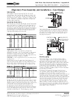
DO NOT apply ANTI-SEIZE
on these areas.

high-speed shaft by dividing the tightening torque 

indicated in Table 3 by the drive’s ratio (Torque ÷ 

Ratio). Apply the calculated torque to the high-

speed shaft or coupling using a spanner, chain or 

pipe wrench. Be careful not to damage the usable 

length of  the high-speed shaft. Remove the fixed 

wrench from the TA bushing nut and reassemble the 

backstop if  necessary.

WARNING

: Never use the prime mover to produce 

the required torque. This could result in severe 

personal injury or damage.

Apply Loctite 243 or equivalent to threads of  

setscrew. Tighten the setscrew to 10 Nm (90 lb-in) 

on the bushing nut. For drives subjected to vibratory 

conditions refer to Step c.

c. 

DRIVES SUBJECTED TO VIBRATORY 

CONDITIONS

 — Extra precautions should be 

taken for drives subjected to vibratory conditions. 

With the nut of  the TA bushing tightened to the 

specified torque, locate the setscrew hole in the 

nut of  the bushing assembly. Using a 6 mm (15/64 

inch) diameter drill, create a dimple in the outside 

diameter of  the bushing flange by drilling through 

the setscrew hole in the nut. Apply Loctite 243 or 

equivalent to threads of  setscrew and tighten into 

bushing nut.

d. 

DRIVES USING THRUST PLATE KIT

 — Install 

thrust plate and thrust plate retaining ring in hollow 

shaft. Coat four to five engaging threads of  retention 

fastener with Loctite 222 or equivalent (low-strength) 

thread locking compound and thread into driven 

shaft end until snug tight. Reinstall shaft cover.

Removal of Shaft-Mounted Drives 

Sizes M1130 - M1190

WARNING

: Lock out power source and remove all external 

loads from drive before servicing drive or accessories.

1.  Drain the lubricant from the drive.
2.  Remove safety guards and belts (if  so equipped). 

Remove hollow shaft cover if  thrust plate kit is used.

3.  Remove motor and motor mount (if  so equipped).
4.  Remove backstop (if  so equipped).

WARNING

: Drive must be supported during removal 

process. Use a sling and take up the slack before 

proceeding.

5.  Remove the setscrew(s) on the bushing nut, which 

is located at the output end of  the hollow shaft. On 

drives using the thrust plate kit, remove the driven shaft 

retention fastener.

6.  Use a spanner, pipe or chain wrench to loosen 

the bushing nut. Initially the nut will freely rotate 

counterclockwise approximately 180° as the nut moves 

from the locked position to the removal position. At this 

point, anticipate resistance which indicates unseating 

of  the bushing. Continue to rotate the nut until it is free 

from the hollow shaft. If  unable to release the drive from 

the driven shaft with the bushing nut, the thrust plate 

kit using a backing bolt (threaded into the driven shaft 

tapped hole) and removal bolt (threaded into the thrust 

plate tapped hole) may be used to release the drive 

from the driven shaft. Refer to Appendix G for backing 

and removal bolt sizes (user supplied). To use, remove 

Содержание Falk Drive One DB

Страница 1: ...s LLC the Company warrants that Drive One gear drives I conform to Company s published specifications and II are free from defects of material for three years from the date of shipment Company does not warrant any non Company branded products or components manufacturer s warranty applies or any defects in damage to or failure of products caused by I dynamic vibrations imposed by the drive system i...

Страница 2: ...ately aligned at the Factory with the bedplate mounted on a large flat assembly plate Shim under the bedplate foot pads until the gear drive is level and all feet are in the same plane Check high speed shaft coupling alignment If the coupling is misaligned the bedplate is shimmed incorrectly Re shim bedplate and recheck high speed coupling alignment If necessary realign motor Shaft Mounted Drives ...

Страница 3: ...0 110 0 0 0 140 129 334 129 784 109 860 110 000 M1160 135 0 0 0 160 146 674 147 264 134 840 135 000 130 0 0 0 160 144 314 144 784 129 840 130 000 125 0 0 0 160 141 814 142 284 124 840 125 000 120 0 0 0 160 139 334 139 784 119 860 120 000 M1170 150 0 0 0 160 164 193 164 773 149 840 150 000 140 0 0 0 160 159 193 159 773 139 840 140 000 130 0 0 0 160 154 293 154 773 129 840 130 000 M1180 170 0 0 0 16...

Страница 4: ...distance from the nut DO NOT apply ANTI SEIZE on these areas high speed shaft by dividing the tightening torque indicated in Table 3 by the drive s ratio Torque Ratio Apply the calculated torque to the high speed shaft or coupling using a spanner chain or pipe wrench Be careful not to damage the usable length of the high speed shaft Remove the fixed wrench from the TA bushing nut and reassemble th...

Страница 5: ... ring and thrust plate from the hollow shaft 3 Select the backing bolts from the table above and install them into the three threaded holes in the end of the driven shaft The head of the backing bolts provides a working surface for the removal bolts 4 Re insert the thrust plate and retaining ring into the hollow shaft and select the removal bolts from the table above 5 Thread three removal bolts i...

Страница 6: ...gnment and assembly of coupling Steelflex Illustrated RIGHT WRONG LEVEL GEAR DRIVE WALL SQUARE AND PARALLEL Fastener Tightening Torques Use the tightening torque values specified in Table 4 for fastening Falk gear drives motors and accessories to their mounting surfaces with un lubricated fasteners DO NOT use these values for torque locking fasteners or for fastening components with aluminum feet ...

Страница 7: ... HP 750 Teresso 150 Dectol R O Oil 220 Teresstic 220 Hydro Drive HP 1000 Teresso 220 Dectol R O Oil 320 Teresstic 320 Teresso 320 Dectol R O Oil 460 Teresstic 460 Kendall Refining Co Keystone Lubricants Lyondell Petrochemical ARCO Mobil Oil Corp Pennzoil Products company Petro Canada Products Four Seasons AW 150 KLC 40 Duro 150 DTE Oil Extra Heavy Pennzbell AW Oil 150 Premium R O 150 KLC 50 Duro 2...

Страница 8: ... AGMA Viscosity Grade 0S 2S 4S 5S 6S 7S ISO Viscosity Grade 32 68 150 220 320 460 Viscosity cSt 40 C 28 8 35 2 61 2 74 8 135 165 198 242 288 352 414 506 Viscosity SSU 100 F 134 164 284 347 626 765 918 1122 1335 1632 1919 2346 Manufacturer Lubricant Chevron U S A Inc Clarity Synthetic PM Oil 220 Syn Gear Lube Tegra 150 Syn Gear Lube Tegra 220 Syn Gear Lube Tegra 320 Syn Gear Lube Tegra 460 Conoco I...

Страница 9: ...iderations If a drive is equipped with an oil pump fill the drive to the level marked on the dipstick Run the lubrication system for several minutes to fill the system components Verify that the pump is circulating oil properly then recheck oil level If necessary add oil to compensate for filter and or cooler Before starting the gear drive rotate the input shaft to check for obstructions Then star...

Страница 10: ... the food processing industry A grease that meets the USDA H1 classification is suitable for food processing applications CAUTION Rapid greasing with a power grease gun can force grease inward past the seals causing seal leaks GREASE LUBRICATED BEARINGS TYPES DV AND DX Most vertical low speed shaft drives have a grease lubricated lower low speed bearing Grease bearings during oil changes or at int...

Страница 11: ...torstor quantities Rotate the shafts several times by hand Before operating drives which have been stored or inactive must be filled to the proper level with oil meeting the specifications given in this manual Refer to Manual 128 014 for Start up after Storage instructions Periodically inspect stored or inactive gear drives and spray or add rust inhibitor every six months or more often if necessar...

Страница 12: ...ype D Series Sizes M1130 thru M1210 168 050 Rexnord Industries LLC 3001 W Canal St Milwaukee WI 53208 4200 January 2019 Telephone 414 342 3131 Fax 414 937 4359 Supersedes 04 11 e mail info rexnord com web www rexnord com PN 2124650 THIS PAGE INTENTIONALLY LEFT BLANK ...

Страница 13: ...racket should be added to the structure after the drive has been secured to the driven equipment NOTE Do not fasten the torque to the support structure at this time 2 Secure the drive to the driven equipment via the TA bushing or rigid coupling connection 3 Check that the torque arm remains perpendicular and centered in the clevis if mounted If the torque arm is not perpendicular and centered repo...

Страница 14: ...to the driven equipment NOTE Do not fasten the torque arm to the support structure at this time 2 Secure the drive to the driven equipment via the TA Bushing shrink disc or rigid coupling connection 3 Mount the anchor bracket or clevis to the drive or drive system if not already done Locate the position of the anchor bracket to be mounted to the support structure Match drill the mounting holes for...

Страница 15: ...IN ROD END MALE ROD END FEMALE TORQUE ARM PIN MOUNTING HARDWARE SUPPLIED BY CUSTOMER Figure 1 ANCHOR BRACKET RETAINING RING SPACER ROD END ROD END SPACER RETAINING RING ANCHOR BRACKET MOUNTING HARDWARE PROVIDED TORQUE ARM PIN JAM NUT TURNBUCKLE JAM NUT TORQUE ARM PIN MOUNTING HARDWARE SUPPLIED BY CUSTOMER Figure 3 CROWNED TORQUE ARM PIN CLEVIS ROD END ANCHOR BRACKET RETAINING RING JAM NUT TORQUE A...

Страница 16: ...g screw holes are provided in gear drive housing to aid in fixing the shims Begin at the low speed shaft end and level across the length and then the width of the gear drive Use a feeler gauge to ensure that all pads are supported Bolt down the drive to the torque specified in Table 4 page 6 Mounting Motor and Coupling Alignment Shims are provided for motor mounting Holes must be drilled into the ...

Страница 17: ...nstall the fluid coupling on the high speed shaft of the gear drive per fluid coupling instructions If a shaft fan is required remove every other of the twelve delay fill chamber fasteners Install the fan adapter ring to the fluid coupling using the long socket head cap screws provided Place a mounting post between the delay fill chamber flange and the adapter ring as shown in Figure 1 After all f...

Страница 18: ...te on the bell housing before installing the coupling Once the motor is secured measure the distance D between the end of the motor shaft and the high speed shaft of the drive See Figure 4 Subtract the distance D from the length of the spacer coupling BE Then divide this value in half to find the overhang of each hub Overhang BE D 2 The overhang will be negative This is the amount each hub overhan...

Страница 19: ...N Do not over tighten fasteners into plastic fan as fan may crack Mount the fan hub on the gear drive high speed shaft such that the set screw hole in the hub is towards the end of the shaft Locate the hub axially at the values listed in Table 2 Dimensions listed are from the inside face of the bell housing to the far side of the hub See Figure 1 Apply Loctite 242 or equivalent to threads of the s...

Страница 20: ...ate Carriage may be adjusted from center to either far end of the housing to facilitate installation of pin Ensure that adjusting rod locking plate is NOT installed at this time as it will prevent adjustment of the torque arm assembly Assemble anchor bracket to male rod end with a spacer on each side and secure with pin and retaining ring Lifting the Alignment Free Drive Lifting points are provide...

Страница 21: ...s the National Electrical Code NEC and Occupational Safety and Health Act OSHA 4 Fan motor must be securely and adequately grounded 5 All working parts should be grounded 6 When cleaning electrical equipment always use an approved cleaning agent See CLEANING in NOTES section page 22 7 For general ventilation and cooling use only Do not use if hazardous or explosive materials and vapors are present...

Страница 22: ...2 POSITION A POSITION B POSITION C 1 1 2 Mounting Positions For Position A B Remove Plug 1 For Position C Remove Plug 2 Note Never use copper or brass fastening materials Figure 3 8 Connect power to the motor using an approved wiring method See Figure 1 for connection diagrams 9 Before starting the fan double check to ensure there are no obstructions that could interfere with proper fan operation ...

Страница 23: ... cadmium plated mild steel with Buna N seal rings Water connections are 500 14 NPT fittings located at the high speed end The water outlet is located on the high speed end of the drive The water inlet connection is a straight fitting located on the lowest cooling tube in the drive The water outlet connection is a right angle fitting faced up located on the uppermost tube in the drive The cooling t...

Страница 24: ...d by flushing with commercially available cleaning compounds such as Oakite or Dowell The commercially available cleaning compounds are corrosive and must be used in accordance with their manufacturer s recommendations Cleaning may also be accomplished by means of a rod or wire brush Remove the tube end seal ring fittings Figures 7 8 on page 25 and pass a 500 12 mm diameter rod or wire brush throu...

Страница 25: ... installed in series with a ball valve to limit maximum water flow Refer to Figure 6 for recommended plumbing diagram The water flow control valve will control water flow rates to less than 2 gallons 8 liters per minute however the cooling tubes will be subject to increased fouling and may require cleaning at more frequent intervals WATER SUPPLY 2 GPM MIN 8 LITERS PER MIN 90 F 32 C MAX TEMP WATER ...

Страница 26: ... 00 M20 x 2 5 x 40 750 10 x 1 50 M24 x 3 x 70 M24 x 3 x 70 341 13 43 284 11 18 M1140 M24 x 3 x 90 1 000 8UNC x 3 50 M24 x 3 x 45 1 00 8 x 2 00 M30 x 3 5 x 80 M30 x 3 5 x 80 386 15 20 319 12 55 M1150 M24 x 3 x 90 1 000 8UNC x 3 50 M24 x 3 x 45 1 00 8 x 2 00 M30 x 3 5 x 80 M30 x 3 5 x 80 406 15 98 334 13 15 M1160 M24 x 3 x 90 1 000 8UNC x 3 50 M24 x 3 x 45 1 00 8 x 2 00 M30 x 3 5 x 80 M30 x 3 5 x 80...

Страница 27: ...G 1 EACH END SEALED WITH LOCTITE PIPE JOINT COMPOUND 30557 P N D004945 1B SQUARE HEAD MAGNETIC DRAIN PLUG 1 EACH END SEALED WITH LOCTITE PIPE JOINT COMJPOUND 30557 P N D004945 5B INSPECTION COVER IF COVER WAS REMOVED APPLY A CONTINOUOUS BEAD OF LOCTITE 515 GASKET ELIMINATOR P N 99409561 OR EQUIVALENT TO HOUSING INSPECTION COVER BOLTING SURFACE MAKE SURE THAT THE BEAD IS LOCATED INSIDE THE BOLT PAT...

Отзывы: