background image

4, 8 &16 Channel Digital Video Recorder 


3

Chapter 2 — Installation & Configuration 


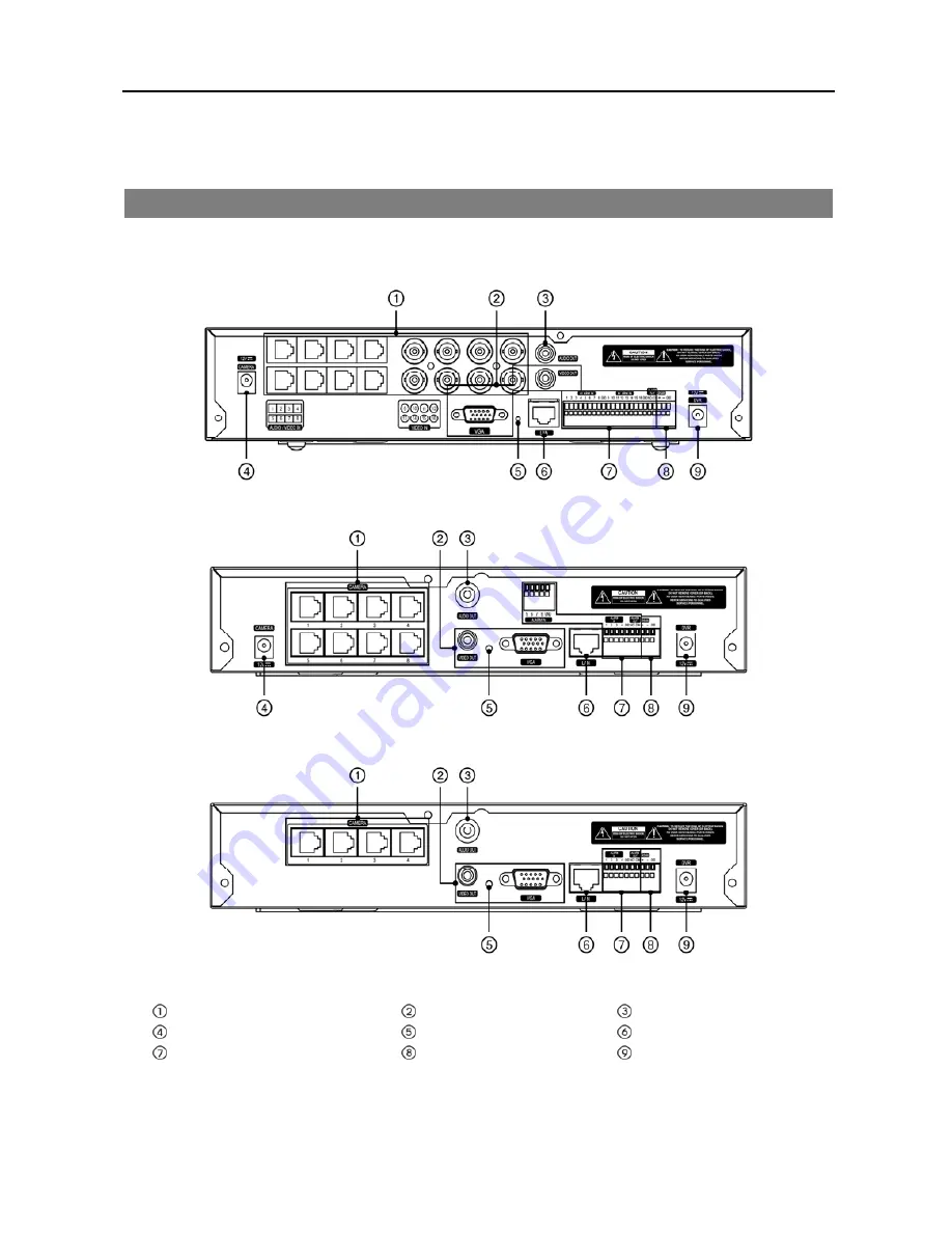
REAR PANEL CONNECTORS 


No special tools are required to install the DVR.  Refer to the installation manuals for the other components that make 
up part of your system.  Your DVR should be completely installed before proceeding. 


16-Channel Model 


8-Channel Model 


4-Channel Model 


  Video In 


Video Out 

 Audio Out


Camera Power Connector 

  Factory Reset Switch 

 Network Port


 Alarm Input/Output

  RS-485 Port

DVR Power Connector 


Содержание 16 Channel

Страница 1: ......

Страница 2: ......

Страница 3: ...PMENT GENERATES USES AND CAN RADIATE RADIO FREQUENCY ENERGY AND IF NOT INSTALLED AND USED IN ACCORDANCE WITH THE INSTRUCTION MANUAL MAY CAUSE HARMFUL INTERFERENCE TO RADIO COMMUNICATIONS OPERATION OF THIS EQUIPMENT IN A RESIDENTIAL AREA IS LIKELY TO CAUSE HARMFUL INTERFERENCE IN WHICH CASE USERS WILL BE REQUIRED TO CORRECT THE INTERFERENCE AT THEIR OWN EXPENSE WARNING CHANGES OR MODIFICATIONS NOT ...

Страница 4: ...ified service personnel under the following conditions A When the power supply cord or the plug has been damaged B If liquid is spilled or objects have fallen into the equipment C If the equipment has been exposed to rain or water D If the equipment does not operate normally by following the operating instructions adjust only those controls that are covered by the operating instructions as an impr...

Страница 5: ...Setup 13 System Setup 14 Network Setup 17 Camera Setup 20 Record Setup 21 Event Setup 23 Display Setup 26 Chapter 3 Operation 29 Live Monitoring 29 Display Menu 31 Event Monitoring 32 Active Cameo Mode 32 PTZ Mode 32 Recording Video 33 Playing Recorded Video 34 Searching Video 35 Search 36 Go To 39 Bookmarks 39 Export 40 REVO Remote 41 Web Monitoring 42 Web Search 43 Appendix 45 Error Code Notices...

Страница 6: ...User s Manual iv ...

Страница 7: ...rol User friendly Graphical User Interface GUI Menu System Multiple Recording Modes Time lapse Pre event Motion Alarm and Panic Multiple Search Engines Date Time Event Record Table Audio Monitoring Capable 8 Channel Audio Recording and 1 Channel Audio Playback Alarm Connections Include Input and Output 2 USB 2 0 Ports Built in Buzzer Live or Recorded Video Access via Ethernet Self diagnostics with...

Страница 8: ...SB Mouse Infrared Remote Control and Batteries REVO Remote Pro Software CD and User s Manual This document NOTE The adaptor and power cord for camera are only for the 8 and 16 channel DVRs Digital Video Recorder Power Adaptors Power Cords USB Mouse IR Remote Control and Batteries AAA Type REVO Remote Pro Software CD and User s Manual ...

Страница 9: ...he DVR Refer to the installation manuals for the other components that make up part of your system Your DVR should be completely installed before proceeding 16 Channel Model 8 Channel Model 4 Channel Model Video In Video Out Audio Out Camera Power Connector Factory Reset Switch Network Port Alarm Input Output RS 485 Port DVR Power Connector ...

Страница 10: ...r to the observation camera manual for configuring the Audio In connection Your DVR can record audio from up to eight sources Connecting the Observation Camera Power Cord The CAMERA power connector is provided to supply power to the observation cameras 8 and 16 chl models only Connect the connector of the adaptor to the DVR and connect the AC power cord to the adaptor and then to the wall outlet F...

Страница 11: ...s to be detected GND Ground Connect the ground side of the alarm input and or alarm output to a GND connector NOTE All the connectors marked GND are common NO Relay Alarm Output Connect the device to the COM and NO Normally Open connector NO is a relay output which sinks 1A 30VDC NO Connector Pin Outs Alarm In 1 to 16 Alarm Inputs 1 to 16 GND Chassis Ground NO Alarm Out Normally Open COM Common Co...

Страница 12: ...nothing blocks the sensor or the remote control will not function properly NOTE When you use wireless communication devices such as Wi Fi or Bluetooth near the DVR the remote control might not function properly HDD LED The HDD LED flickers when the DVR is recording or searching video on the hard disk drive Power LED The power LED is lit when the unit is On Alarm LED The Alarm LED is lit when alarm...

Страница 13: ...tting the System ID If the DVR system ID is 1 to 16 you must to press the ID button on the remote control followed by the number button 1 to 16 10 6 in order to control that DVR If two or more DVRs have the same ID those DVRs will react to the infrared remote control at the same time CAMERA Buttons 1 to 16 Pressing the individual camera buttons will cause the selected camera to display full screen...

Страница 14: ...DVR is in the Pause mode and the screen displays when the DVR is playing back video Fast Forward Pressing the button plays video forward at high speed Pressing the button again toggles the playback speed from and Stop Pressing the button stops playback and enters the Live Monitoring mode Backward When in the pause mode pressing the button moves to the previous image Forward When in the pause mode ...

Страница 15: ...language during System setup Refer to the Advanced Setup section of this chapter Before using your DVR for the first time you will want to establish the initial settings The following describes how to use the remote control and mouse in the setup screen Take a minute to review the descriptions Remote Control Mouse To enter the setup screen In Live Monitoring mode press the MENU button to display t...

Страница 16: ...an be accessed by selecting Quick Setup in the Main Setup screen Refer to the following Advanced Setup section Select the Next button to start the Quick Setup Wizard NOTE Selecting the Cancel button throughout the screens exits the Quick Setup Wizard without saving your changes and return to the Live Monitoring mode Date Time Setup Date Set the system date and select the date format Time Set the s...

Страница 17: ...ecord Very High 30 ips Time Very High 30 ips Post Event High 5 ips Time Very High 30 ips Post Event Standard 3 ips Time High 5 ips Post Event Continuous Record Very High 30 ips High 5 ips Time Standard 3 ips 4 and 8 ch Models HVQPP SRP LRTPP Motion Event Record Very High 30 ips High 5 ips Standard 2 5 ips Continuous Motion Event Record Very High 30 ips Time Very High 30 ips Post Event High 5 ips T...

Страница 18: ...Selecting Manual Configuration allows you to set up LAN parameters manually NOTE The network configuration you set should be tested by selecting Test otherwise the Next button will cannot be selected and you cannot move to the next step Use DSL PPPoE Setup Selecting the box allows you to set up the DSL network Entering the ID and password for DSL connection is required REVO Dashboard Setup I Selec...

Страница 19: ... appears Select a User and enter the password by pressing the appropriate combination of Camera number buttons on the remote control and select the OK button The factory default password is 1234 for a User and there is no password for an admin user If you do not know the password click the button for guidance NOTE When logged on as the User live monitoring searching video and exporting recorded da...

Страница 20: ...u must format the hard disk drive SYSTEM SETUP System Settings SYSTEM System Tab System ID Set the system ID Use the Up and Down arrow buttons or scroll the mouse wheel to increase or decrease the number NOTE It is possible to have multiple DVRs with the same System ID in the same area In this case all DVRs with the same System ID will be controlled at the same time when using the infrared remote ...

Страница 21: ...en displays Select the box beside File name and press the button A virtual keyboard allows you to enter the file name Selecting Export will save the log information in txt file format on the USB device Log Message Log Message Log Message Boot Up Setup Export Cancel Backup End Local Remote Upgrade Local Schedule On Backup Cancel Local Remote Upgrade Failure Local Schedule Off Backup Failure Local R...

Страница 22: ...ntage of bad disk sections is damaged Temperature Displays the temperature of the storage drive N A The DVR cannot read the temperature Good The temperature does not exceed the user defined temperature threshold Bad The temperature exceeds the user defined temperature threshold S M A R T Displays S M A R T Self Monitoring Analysis and Reporting Technology information of the storage Good The storag...

Страница 23: ... or out of synchronization during transmission Network Bandwidth Limit You can limit the network bandwidth settings so that system does not consume too much network bandwidth Set the desired maximum bandwidth from 10Kbps to 100Mbps NOTE When limiting the network bandwidth the remote watch image on the PC running REVO Remote Pro or REVO Remote might not be displayed properly Enable SSL for Transfer...

Страница 24: ... server instead of the IP address can be used during DVRNS Server or Mail setup Checking the Auto Default box allows the DVR to obtain the IP address of the DNS server automatically 16 ch model only NOTE Selecting Auto will only be enabled when the DVR is configured for DHCP or an ADSL network Port Number Setup Set the port number of each remote software related program NOTE You will need to get t...

Страница 25: ...r the DVR name to be registered on the DVRNS server Check whether or not the name you entered is available by selecting the Check button NOTE The DVR name you entered should be checked by selecting the Check button otherwise the DVRNS changes will not be saved When no name is entered or a name is already registered on the DVRNS server an error message displays Help Desk Selecting the Save button r...

Страница 26: ...ator You can use the domain name instead of IP address if you set up the DNS server during Network setup Port Set the SMTP server port number obtained from your system administrator Use SSL TLS Check the box when sending an e mail via an SMTP server requiring SSL Secure Sockets Layer authentication Authentication Select the button if the SMTP server needs authentication and set up the Authenticati...

Страница 27: ...t the length of time recorded data will be kept by using the slide bar or Up and Down arrows buttons Selecting Never will disable the Auto Deletion function The DVR automatically deletes video recorded earlier than the user defined period under three conditions at midnight whenever the system reboots or whenever the user changes the Auto Deletion settings NOTE The following description is for 4 an...

Страница 28: ...s you to set recording settings for all camera channels at one time The Advanced schedule mode allows you to set recording settings for each camera channel Setting up the Basic Schedule Mode Schedule Type Select the Basic schedule mode Record Schedule Select the time range that the scheduled recording will take place Mode Select the desired recording mode Time Time lapse recording yellow Pre Event...

Страница 29: ... and Channels that are not defined will use the setting values of the previous schedule item NOTE When more than two schedule items are registered in the same day and time range the DVR will follow the latest registered schedule item EVENT SETUP Motion Event Settings EVENT Motion Tab No Your DVR has built in motion detection Selecting the box turns the motion detection On and Off for each camera S...

Страница 30: ...ted camera Motion event can sound the external alarm or DVR s internal buzzer notify a number of different devices and or move PTZ cameras to preset positions Alarm Out Select the alarm out signals Alarm Out and Beep to be associated with the camera Notify Select Mail if you want to send an e mail to the address set during NETWORK Mail setup PTZ Select the preset position for each PTZ camera where...

Страница 31: ...you to add a check recording schedule by setting the day time range and interval that you want the DVR to run self diagnostics on the recorder Selecting allows you to delete a check recording schedule Check Alarm In Selecting the column allow you to change interval the DVR to run self diagnostics on alarm inputs Disk Almost Full Select the percentage level of disk usage at which you want the DVR t...

Страница 32: ...TZ The icon displays on each PTZ camera screen with PTZ capabilities Transparency Adjust the transparency of the setup screens by using the slide bar OSD Margin Set the Horizontal and Vertical margins so that text and icons will display within the edges of the monitor Main Monitor Settings DISPLAY Main Monitor Tab Sequence Mode Select the sequence mode between Full Sequence and Cameo Sequence 8 an...

Страница 33: ... On the DVR will display the camera associated with the event when an event occurs See Chapter 3 Operation Live Monitoring for details VGA Settings DISPLAY VGA Tab Resolution Set the resolution of the VGA monitor Full Screen Displays the VGA monitor in full screen mode 16 ch model only Test Selecting the button allows you to test how the screen will be displayed with the resolution you set ...

Страница 34: ...User s Manual 28 ...

Страница 35: ... screen Freeze Selecting the Freeze icon will freeze the current image on the screen until you select Freeze again It is the same as pressing the FREEZE button on the remote control Selecting the icon again exits the Freeze mode While in the Freeze mode the icon displays in bottom left corner if Freeze is selected in the Display setup screen OSD tab Sequence Selecting the Sequence icon causes the ...

Страница 36: ...e adjustment dialog Selecting Color Control and choosing the camera number is the same as pressing and holding a camera button on the remote control for a few seconds You can control brightness contrast hue and saturation for each camera NOTE Selecting Audio will be enabled on camera screens 1 to 8 16 ch model only NOTE It is important that cameras and monitors are correctly installed and adjusted...

Страница 37: ... 3x3 4x4 Selecting the or PIP 2x2 3x3 or 4x4 icon displays the cameras in the selected multiview screen mode PIP 2x2 3x3 or 4x4 Selecting each display mode is the same as pressing the LAYOUT button on the remote control or scrolling the mouse wheel up and down when in one of the multiview formats i e 2x2 3x3 or 4x4 NOTE The location of camera screen can be changed by using the mouse When in one of...

Страница 38: ... exit the Active Cameo mode by clicking right mouse button and selecting Exit Group Edit in the menu The active cameo mode will remains in effect for 15 seconds if there is no further operation In active cameo mode press the camera button on the remote control for the camera you want displayed as active cameo After setting the camera number to active cameo the DVR moves the active cameo to the nex...

Страница 39: ... on the left side exits the toolbar If you want to display the toolbar again position the mouse pointer at the bottom of the screen Change the toolbar location by clicking the empty space on the left side of the toolbar and dragging it to where you want it located on the screen Use the arrow buttons on the toolbar to pan or tilt the camera in the direction you want The other controls on the toolba...

Страница 40: ...When selecting 11 to 16 press 10 and then press the 1 to 6 Playback Buttons Backward When in the pause mode pressing the button moves to the previous image Forward When in the pause mode pressing the button moves to the next image Rewind Pressing the button plays video backward at high speed Pressing the button again toggles the playback speed from and Play Pause Pressing the button plays back vid...

Страница 41: ...Exit icon at the top of the screen by pressing the MENU button on the remote control or moving the mouse pointer to the top of the screen exits the Zoom mode While in the Zoom mode the icon displays on the camera screen if Zoom is selected in the Display setup screen OSD tab Audio Selecting Audio while in the full screen mode toggles playing recorded audio On and Off While playing recorded audio t...

Страница 42: ...e button will select the event video and display the first image of the event Pressing the Play Pause button on the remote control button will start playing the event video segment If you want to return to live monitoring press the MENU button on the remote control and select the Exit icon at the top of the screen NOTE It is possible no recorded image displays on the current screen Press the LAYOU...

Страница 43: ...rch Standard View Compact View Expanded View Recording information about video images currently displayed on the screen displays in the recording status bar A grey vertical line indicates the current search position To search for specific video move the vertical line by pressing the Left or Right arrow buttons on the remote control scrolling the mouse wheel or clicking the mouse on the desired seg...

Страница 44: ...Interlace Turns the de interlace filter on 4 and 8 ch models only Slow Play Plays video at low speed x1 2 x1 3 x1 4 x1 6 and x1 8 NOTE Playing video at low speed will be supported for video recorded 10 images or more per second Selecting located at the bottom displays the Bookmarks screen see below for more details 16 ch model only Selecting in the top left corner exits the Record Table Search scr...

Страница 45: ...igh sensitivity Min Blocks Set the number of sensor blocks that must be activated Once you set your desired search conditions select Search and press the button to display the search results in the Motion Search screen Selecting Cancel exits the screen without saving the changes When you search for motion events for another camera you will be asked whether or not you want to delete the previous se...

Страница 46: ...a specific Date and Time When set to On the copy will be from the first recorded image When highlighting and pressing the button the bookmark list displays and the bookmark point you selected will be the starting date and time 16 ch model only To Pressing the button toggles between On and Off When set to Off you can enter a specific Date and Time When set to On the copy will be to the last recorde...

Страница 47: ...stem requirements for using the REVO Remote program are Operating System Microsoft Windows XP x86 32 Bit Service Pack 3 Microsoft Windows Vista x86 32 Bit Service Pack 1 Microsoft Windows 7 x86 32 Bit CPU Intel Pentium III Celeron 600MHz or faster RAM 128MB or higher VGA 8MB or higher 1024x768 24bpp or higher Internet Explorer Version 6 0 or later Start Internet Explorer on your local PC You can r...

Страница 48: ...mission speed when using the Microsoft Windows Vista or higher operating system In this situation it is recommended that you disable the Auto Tuning capability of your computer Run the Command Prompt with elevated administrator permissions Go to the Start Menu Accessories Command Prompt Click the right mouse button and select the Run as administrator option Then enter netsh int tcp set global auto...

Страница 49: ... monitor live audio from the connected remote site through the attached speaker and click the button again stop monitoring live audio Clicking both the and buttons allows two way communication Clicking the button disables audio communication Aspect Ratio Changes the image aspect ratio Deinterlacing Using a deinterlace filter for interlaced video enhances image display quality by eliminating horizo...

Страница 50: ... on the screen Selecting the icon allows you to display an image from a specific time Click the icon to enter the event search mode which allows you to search for event log entries using specific conditions and play back the images associated with those event entries Click the icon to save the current image in a bitmap or JPEG file format or click the icon to save any video clip of recorded data a...

Страница 51: ...G PROBLEM POSSIBLE SOLUTION No Power Check power cord connections Confirm that there is power at the outlet No Live Video Check camera video cable and connections Check monitor video cable and connections Confirm that the camera has power Check camera lens settings DVR has stopped recording If hard disk drive is full you will either need to delete video or set the DVR to the Recycle On Recycle Whe...

Страница 52: ...User s Manual 46 MAP OF SCREENS ADVANCED SETUP ...

Страница 53: ...m Input 4 8 or 16 TTL NC NO programmable 4 3V NC or 0 3V NO threshold Alarm Output 1 relay out terminal block NO 1A 30VDC Internal Buzzer 80dB at 10cm Network Connectivity 10 100 Base Ethernet Audio Input RJ 12 Input 8 Line In Audio Output RCA Output 1 Line Out IR Port 1 Remote Control CONNECTORS Video Input 16 ch Model 8 ch Model 4 ch Model 8 RJ 12 12V Max 310mA and 8 BNC 8 RJ 12 12V Max 310mA 4 ...

Страница 54: ...460mm Operating Temperature 41 F to 104 F 5 C to 40 C Operating Humidity 0 to 90 Power 16 ch Model 8 ch Model 4 ch Model DVR 12V 1 9A Adaptor 100 240 V 50 60Hz 1 5A 12V 5A Camera 12V 2 5A Adaptor 100 240 V 50 60Hz 1 5A 12V 5A DVR 12V 1 2A Adaptor 100 240 V 50 60Hz 1 5A 12V 5A Camera 12V 2 5A Adaptor 100 240 V 50 60Hz 1 5A 12V 5A DVR 12V 2 2A Adaptor 100 240 V 50 60Hz 1 5A 12V 5A Camera 12V 2 2A Ad...

Страница 55: ...ime 28 De Interlace 25 DHCP 22 Disk Almost Full 29 Disk Bad 20 29 Disk Temperature 29 DNS 16 DNS Server 22 DSL PPPoE 16 DVRNS DVR Name Service 23 Dwell 26 E Enable De Interlace 38 Enable SSL for Transferring Data 21 Enter Button 12 Event Actions 28 29 Event Log Search 39 Event Log Search Screen 39 Event Monitoring 35 Event Monitoring On 31 Event Setup 27 Export 18 38 F Factory Reset 8 FAT16 19 FAT...
Страница 56: ...a 20 Recycle On Recycle Off 36 Recycle When Disk Full 25 Remote Search 44 46 Remote Watch 44 45 Resolution 25 RJ 12 8 RS 485 9 RTP 23 RTSP 23 S S M A R T 20 Search Mode 34 Sequence 32 Sequence Button 11 Setup 33 Setup Import 18 Show System Log 19 Slow Play 41 SMTP Server 22 24 Standard CIF High Half D1 Very High D1 36 Storage Setting 20 Subnet Mask 16 System Event Setting 29 System ID 18 System Se...

Отзывы: