19
6. Maintenance
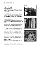
Fig. 6.4
Fig. 6.5
Fig. 6.6
C
B
A
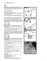
Fig. 6.7
A
The cutter block in this machine is designed to hold three blades.
Never attempt to use the machine if any of the blades are
missing or damage. All blades used must conform to BS EN 847-1.
Changing the Planer Blades
Check the height of the Blade
The blades should be periodically replaced or adjusted. Adjustments should
be as precise as possible with tolerances within 1- 1.1mm to prolong the
sharpness of the blades edges.
Improperly adjusted Blades can unbalance the cutterblock and shorten
bearing life, as well as produce substandard thicknessing or planing results.
The planer blades fitted to this machines are made from high speed steel
and can be reshaped periodically to maintain the cutting edge and optimise
performance of the machine. The process of resharpening blades will
remove a small amount of material from the blade's edge and therefore
will reduce the overall width of the blade. Never attempt to use blades that
have been reduced by more than 25% of their original width. Always ensure
that the blade can be held securely by the blade holder. Replace deffective
blades immediately.
Caution: Before carrying out any adjustments or maintenance
ensure that the machine is isolated and disconnected from the
electricity supply.
1. Remove the cutter-block guard to expose the top of the cutter-block.
2. Carefully turn the cutter-block until the first blade is at top dead centre.
3. Using the cutter-block gauge check the blade height.
The gauge should sit solidly with the pads resting on the cutter-block. If the
knife is adjusted properly, the knife is barely touching the middle slot of
cutterblock gauge. If the knife does not touch the middle slot, or if the knife
causes the pads of gauge to not sit flush on the cutter-block, the knives
need to be adjusted. The Blades should protrude from the cutter block by a
maximum of 1.1mm.
Changing the blades
Caution: Before carrying out any adjustments or maintenance
ensure that the machine is isolated and disconnected from the
electricity supply.
1. Remove the cutter-block guard to expose the top of the cutter-block.
2. Carefully turn the cutter-block until the first blade is at top dead centre.
3. Release all blade holder screws (A -
Fig. 6.5
) of each blade, by screwing
them into the blade holder.
4. Remove the blade holder (B -
Fig. 6.5
) and planer blade (C -
Fig. 6.5
)
one at a time.
5. Repeat this process with all blades.
6. Clean the planer blades, blade holders and planer cutter block of traces
of resin as thoroughly as possible.
7. Reinstall the planer blades and blade holders, tighten the blade holder
screws lightly at first.
8. Check the height of blade (see “Check the height of blade”).
9. Turn the jack screw to adjust the height of knife, (
Fig. 6.6
)
10. Finally tighten all blade holder screws, (A -
Fig. 6.5
) by unscrewing
them from the blade holder.
Drive belts
Over time, the drive belt tension may loosen. In this case, the belt must
either be tightened or replaced.
Check the belt monthly for cracks or lateral tears.
Replace the belt if necessary.
Loosen motor mounting bolts A (
Fig 6.7
).
Use the weight of the motor to tension the drive belt. When the correct
tension is applied, tighten the motor mounting bolts A, (
Fig 6.7
).
i
Kg
i
Kg
i
Kg
i
Kg
i
Kg
Содержание PT107
Страница 29: ...29 10 Parts List Diagrams cont ...
Страница 33: ...33 ...


