background image

12

Clean Up 

The unpainted surfaces are coated with a waxy oil to protect them from 
corrosion during shipment. Remove this protective coating with a solvent 
cleaner or citrus  based greaser. To clean thoroughly, some part may need to 
be removed. For optimum performance from your machine, make sure you 
clean all moving parts or sliding contact surfaces that are coated. Avoid
chlorine-based solvents as they may damage painted surfaces should they 
come in contact.

Warning: Do not use gasoline or other petroleum-based solvents 
to clean with. They have low flash points which make them 
extremely flammable. A risk of explosion and burning exists if 
these products are used.

Warning: Do not smoke while using solvents. A risk of explosion 
or fire exists and may result in serious personal injury.

Contents of Carton 

After all the parts have been removed from the carton, you should have:

PT107 main unit
Bridge guard assemby
Fence assemby
Push stick
Cover plate for the  end of the cutter block
Emergency stop cover for switch
Cutter-block setting gauge
3mm allen key
8 & 10mm open end spanner

Fitting the Bridge Guard 

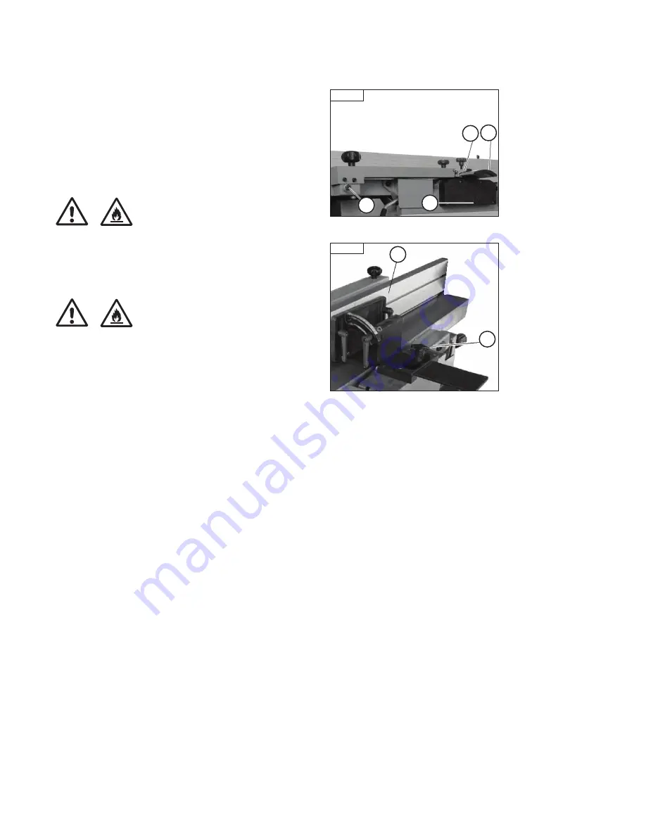
1. Insert the M10x100 hex head screw with spacer (A - 

Fig 4.3

) to mount 

the bridge guard to out-feed table (the washer and lock nut should be fitted 
under the out-feed table).
2. Sliding the protective bridge guard (B - 

Fig 4.3

) into bridge guard support 

bracket (C - 

Fig 4.3

).

3. Then adjust the three star knob screws to keep the bridge 
guard in position.
4. Fit the cover plate (D - 

Fig 4.3

) (under protective guard plate) onto the 

machine frame with 4-pan head screws M6 x 30.

Fitting the Fence (if Needed) 

1. Pull the protective guard (B - 

Fig 4.3

) out as far as possible

2. Place the fence assembly (A - 

Fig 4.4

) onto the planer table and slide the 

fence carrier into the bracket fitted to the machine.
3. Tighten the fence in position with the star knob (B - 

Fig 4.4

).

Fig 4.3

A

C

Fig 4.4

A

B

B

D

4. Assembly

i

Kg

i

Kg

i

Kg

i

Kg

? Picture

Содержание PT107

Страница 1: ...when using woodworking equipment Always read the instructions provided before using woodworking equipment i Kg Version 3 0 January 2013 To register this product please visit www recordpower info It is important to register your product as soon as possible in order to receive efficient after sales support and be entitled to the full 5 year guarantee Your statutory rights are not affected Please see...

Страница 2: ... 5 Operation 6 Maintenance 7 Dust Extraction 8 Electrical Connection Wiring Diagram 9 Troubleshooting 10 Parts List Diagrams EU Certificate of Conformity Terms Conditions Of Usage Explanation of Symbols General Health Safety Guidance Additional Safety Instructions For Planer Thicknessers Record Power Guarantee ...

Страница 3: ...ing to use the machine Indicates an instruction that requires particular attention Wear protective eyewear Use respiratory protective equipment Use suitable protective footwear Use hearing protection Use protective work gloves Indicates a risk of severe personal injury or damage to the machine Indicates a risk of severe personal injury from electrical shock Risk of personal injury from lifting of ...

Страница 4: ...esigned to be fitted to the machine always ensure that it is securely fastened to the machine using the fixings provided If the machine is suitable to be used on a workbench ensure that the workbench is well constructed and capable of withstanding the weight of the machine The machine should always be securely fastened to the workbench with appropriate fixings Where possible floor standing machine...

Страница 5: ...o not attempt to machine more than one work piece at a time When feeding the work piece towards the blade or cutting tool never position your hands in direct line of the cutting path Avoid awkward operations and hand positions where a sudden slip could cause your hand or fingers to move into the machining area 23 Stay alert Safety is a combination of operator common sense and alertness at all time...

Страница 6: ...the warranty 32 Have your machine repaired by a qualified person This machine complies with the relevant safety rules and standards appropriate to its type when used in accordance with these instructions and with all of the standard safety guards and equipment in place Only qualified persons using original spare parts should carry out repairs Failure to do this may result in considerable danger to...

Страница 7: ...safety guards Keep guards operational at all times Use extra caution with large very small or irregularly shaped work pieces Use extra supports roller support stands etc for any work pieces large enough to tip when not held down to the table top Do not use another person as a substitute for a table extension or as additional support for a work piece that is longer than the basic planer table or to...

Страница 8: ...n purchased from a retailer the 5 year guarantee is transferable and begins on the date of the first purchase of the Product and in the event of a claim under this guarantee proof of the original purchase date will be required to validate the warranty period 2 Claims Procedure 2 1 In the first instance please contact the Authorised Dealer who supplied the Product to you In our experience many init...

Страница 9: ...130 mm fence pivot 90º 45º dust port diameter 100 mm weight 162 kg Noise level Sound power level 85 dB A 106 dB A Unloaded loaded Sound pressure level 83 dB A 100 dB A Unloaded loaded MOTOR 230 V 50 Hz 3 hp 2200 W Full load current 9 7 A 2 Getting to Know your Machine 1 Fence 2 Outfeed table 3 Infeed table 4 Table lock 5 Protective guard 6 Bridge guard arm 7 Adjustable knob guard 8 Dust hood 9 Thi...

Страница 10: ...stomer Service immediately for advice When you are completely satisfied with the condition of your shipment check all parts are present The planer thicknesser is a heavy machine DO NOT over exert yourself while unpacking or moving your machine You will need assistance and power equipment to move the machine Serious personal injury may occur if safe moving methods are not followed Warning Never lif...

Страница 11: ...rocess using two hex nuts being placed through the pilot holes in the machine body and secured in place by two nuts Fig 4 5 When the wheel kit is not in use the wheels fitted to the main body of the machine can be raised by unscrewing the adjusting screw Fig 4 4 A so that they are clear of the surface of the floor The wheels should be lowered again before attempting to use the wheel kit Never atte...

Страница 12: ... carton you should have PT107 main unit Bridge guard assemby Fence assemby Push stick Cover plate for the end of the cutter block Emergency stop cover for switch Cutter block setting gauge 3mm allen key 8 10mm open end spanner Fitting the Bridge Guard 1 Insert the M10x100 hex head screw with spacer A Fig 4 3 to mount the bridge guard to out feed table the washer and lock nut should be fitted under...

Страница 13: ...ak Working techniques Permitted working techniques All uses deviating from those described below are considered improper uses and are therefore not permitted Planing the wide side of a workpieces Planing the narrow side of a workpieces Bevelling the edges of a workpieces Prohibited Working Techniques The following work techniques are prohibited on the machine Down cut jointing direction of arbor r...

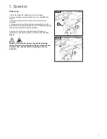
Страница 14: ...ation See Fig 5 4 for illustration of a knife at top dead centre 3 Place a straightedge across the out feed table so the end of the straightedge is directly over the knife Fig 5 5 4 If the out feed table is set correctly the straightedge will lay across the table and barely touch the knife when it is at top dead centre see illustration in Fig 5 5 Verify that the out feed table height reflects this...

Страница 15: ...oints The width of the work piece Type of wood hardwood or softwood Wood dampness Condition of planer blades Planer blade Rear Planer Fence Guard This guard A Fig 5 8 is an integral part of the planer fence B Fig 5 8 so it will always be positioned over the planer cutter block If necessary adjust the planer fence across the cutter block by unscrewing the star knob screw C Fig 5 8 Working technique...

Страница 16: ... from the angled surface press the workpiece mainly against the fence and only lightly against the planing table Planing surfacing of small work piece When surfacing or planing small work pieces use pushing strips A and a push block B Fig 5 13 The push strip should not be thicker than the workpiece Tapering beveling small work piece You must always use a special jig for beveling small narrow work ...

Страница 17: ...nail or the work piece become extremely tapered switch off the feed immediately and lower the thicknessing table to free the workpiece A maximum of 2 work pieces can be fed through the thicknesser simultaneously These must be pushed in at each end of the feed roller Fig 5 16 Warning If the workpiece becomes trapped when feeding into the thicknesser immediatelly switch the machine off and disconnec...

Страница 18: ...operated maintained and repaired in accordance with the instructions provided This machine must be checked periodically Defective equipment including power cable should not be used Parts that are broken missing plainly worn distorted or contaminated should be replaced immediately Should such repair or replacement become necessary it is recommended that such repairs be carried out by qualified pers...

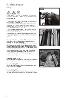
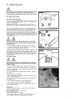
Страница 19: ... sit solidly with the pads resting on the cutter block If the knife is adjusted properly the knife is barely touching the middle slot of cutterblock gauge If the knife does not touch the middle slot or if the knife causes the pads of gauge to not sit flush on the cutter block the knives need to be adjusted The Blades should protrude from the cutter block by a maximum of 1 1mm Changing the blades C...

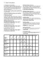
Страница 20: ... e if one motor is switched off for 20 minutes then the other can be used thus enabling continuous usage Or both motors can be used simultaneously giving maximum suction but in this mode the extractor must be switched off for 20 minutes every hour 0 5 micron filtration suitable for MDF DX5000 High Filtration Dust Extractor Bag type extractor 200 litre capacity twin 1 kW motor suitable for heavy us...

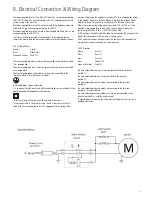
Страница 21: ...S1363 plug for use in the UK always ensure that it is fitted with a fuse conforming to BS1362 appropriate to the rating of the machine If replacing the original fuse always fit a fuse of equivalent rating to the original Never fit a fuse of a higher rating than the original Never modify the fuse or fuse holder to accept fuses of a different type or size Where the current rating of the machine exce...

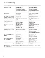
Страница 22: ...rcuit breaker is tripped 4 Motor cord or switch is damaged 5 Microswitches not made 1 Plug in power cord to volt electrical outlet 2 Replace circuit fuse 3 Reset circuit breaker 4 Have the motor cord or switch replaced 5 Switch microswitch Power Switch does not operate 1 Power switch contacts are burned out 2 Capacitor is defective 3 Wiring conne ctions are loose or damaged 1 Have the power switch...

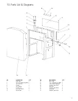
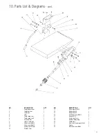
Страница 23: ...ock lever 1 4 Oil seal 1 8 Seat bearing 1 9 Hex lock nut 3 10 Hex screw M6x16 5 11 Washer 6mm 2 NO DESCRIPTION Q TY 12 Inner shield 1 13 Cross sunk head screw M5x6 5 14 Scale thicknessing height 1 15 Pan head screw M5x6 5 16 Gear cover 1 17 Pan head screw M5x6 6 18 Cover plate 2 19 Pan head screw M5x8 4 ...

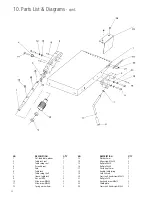
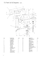
Страница 24: ...e table lock 1 9 Hex nut M16 2 10 Allen screw M6x20 3 11 Allen screw M8x25 2 12 Spring washer 8mm 3 NO DESCRIPTION Q TY 13 Washer 8mm 3 14 Allen screw M8x30 2 15 Roll pin D6x20 2 16 Roll pin D6x30 1 17 Circle ring 12mm 1 18 Handle table swing 1 19 Safe link rod 1 20 Cross sunk head screw M5x12 1 21 Roll pin 5x10 1 22 Hex head screw M6x12 2 23 Shield plate 1 24 Cross sunk head screw M6x8 2 ...

Страница 25: ... seat 1 8 Sleeve table lock 1 9 Allen screw M6x20 3 10 Allen screw M8x30 2 11 Spring washer 8mm 3 12 Washer 8mm 3 NO DESCRIPTION Q TY 13 Allen screw M8x25 2 14 Roll pin D6x30 1 15 Roll pin D6x20 2 16 Hex head screw M6x12 2 17 Hex nut M16 2 18 Circle ring 12mm 1 19 Handle table swing 1 20 Shield plate 1 21 Cross sunk head screw M6x8 2 22 Pointer 1 23 Pan head screw M4x8 1 ...

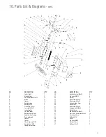
Страница 26: ...uide rod 1 15 Spacer 1 16 Spacer 1 17 Thrust bearing 51102 1 18 Hex lock nut M10 2 19 Spring washer 6mm 2 NO DESCRIPTION Q TY 20 Hex head screw M6x60 2 21 Set screw M8x12 4 22 Oil seal 1 23 Allen screw M8x16 10 24 Allen screw M8x35 4 25 Spring washer 8mm 4 26 Hex nut M6 2 27 Allen screw M6x55 1 28 Carriage bolt M6x40 1 29 Washer 6mm 1 30 Pan head screw M4x10 2 31 Cross sunk head screw M4x8 12 32 C...

Страница 27: ...se guide rod 1 15 Spacer 1 16 Spacer 1 17 Thrust bearing 51102 1 18 Hex lock nut M10 2 19 Spring washer 6mm 2 NO DESCRIPTION Q TY 20 Hex head screw M6x60 2 21 Set screw M8x12 4 22 Oil seal 1 23 Allen screw M8x16 10 24 Allen screw M8x35 4 25 Spring washer 8mm 4 26 Hex nut M6 2 27 Allen screw M6x55 1 28 Carriage bolt M6x40 1 29 Washer 6mm 1 30 Pan head screw M4x10 2 31 Cross sunk head screw M4x8 12 ...

Страница 28: ...cket D 1 14 Shaft sprocket 1 15 Pan head screw M6 x 8 4 16 Circle ring 12mm 1 17 Lever friction wheel 1 18 Hex nut M10 2 NO DESCRIPTION Q TY 19 Spring 1 20 Handle friction lever 1 21 Tension plate 1 22 Tension rod 1 23 Spring 1 24 Washer 10mm 1 25 Bearing 6303 1 26 Feeding chain 1 27 Chain 1 28 Belt XPZ1250 1 29 Motor pulley 1 30 Motor 1 31 Hex head screw w flange M8 x 25 4 32 Special flat washer ...

Страница 29: ...29 10 Parts List Diagrams cont ...

Страница 30: ... Washer 10mm 1 12 Hex lock nut M10 1 13 Hex nut M8 5 14 Allen screw M6x20 2 15 Washer 6 mm 11 16 Hex lock nut M6 5 NO DESCRIPTION Q TY 17 Flat washer 8 mm 1 18 Spring 1 19 Star type screw M6x35 1 20 Star type screw M8x35 1 21 Star type nut 1 22 Cap nut M8 1 23 Allen screw M6x10 2 24 pan head screw M5x65 1 25 Hex lock nut M5 1 26 Spacer 6 27 Cross sunk head screw M6x16 3 28 Hex lock nut M6 2 29 Spa...

Страница 31: ...N 1 Washer 16mm 2 Castor 3 Roll pin 4x30 4 Bracket castor 5 Allen screw M12x50 6 Bracket castor 7 Washer 10mm 8 Hex screw M12x80 9 Washer 12mm 10 Bushnig bracket 11 Support pull rod 12 Hex screw M10x55 12 Pull rod 14 Bolt bracket 15 Shaft castor ...

Страница 32: ...2006 42 EC LOW VOLTAGE DIRECTIVE 2006 95 EC ELECTROMAGNETIC 2004 108 EC COMPATIBILITY DIRECTIVE EN 55014 1 2006 EN 61000 3 2 2006 EN 61000 3 3 1995 A1 A2 EN 55014 2 1997 A1 and conforms to the machinery example for which the EC Type Examination Certificate No BM50170155 AN50170154 has been issued by TUV Rheinland LGA Products GmbH at Tillystrasse 2 D90431 Nürnberg and complies with the relevant es...

Страница 33: ...33 ...

Страница 34: ...k Eire Record Power Ltd Unit B Adelphi Way Ireland Industrial Estate Staveley Chesterfield Derbyshire S43 3LS Tel 01246 561 520 www recordpower co uk Australia Tools 4 Industry Po Box 3844 Parramatta 2124 Tel 1300 124 422 Fax 1800 262 725 www recordpower com au New Zealand Tools 4 Industry Po Box 276079 Manukau City 2241 Tel 0800 142 326 Fax 09 2717 237 www recordpower co nz Made in China ...

Отзывы: