14
Out-feed Table Adjustment
Please note: The height of out-feed table is factory set. It
should only require adjustment in cases where other normal
adjustments to the planer knives have not rectified any
alignment issues.
Please note: Before carrying out any of the adjustments below,
ensure that the machine is switched off and that the power cord
is disconnected from the mains supply.
After several hours running, the outfeed table may need adjustment.
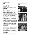
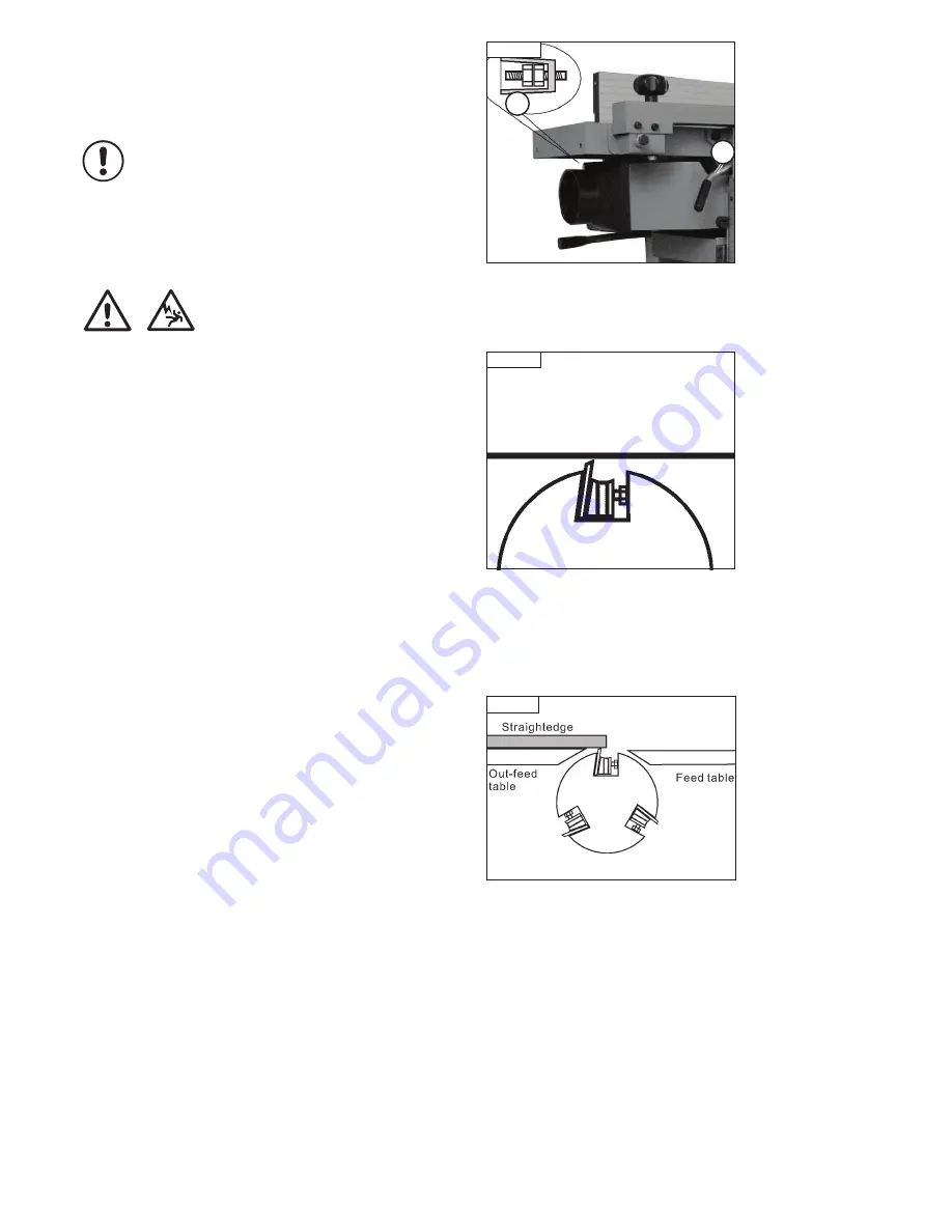
1. Loosen two hex nuts in the adjusting handle (A -
Fig. 5.3
).
2. Open table lock (B -
Fig. 5.3
) and turn adjusting handle, but do not raise
the table.
3. Place a straight edge on the out-feed table, and adjust the table so that it
is 0.1mm lower than the blade at its highest point.
4. Then re-tighten the table lock (B -
Fig. 5.3
) securely, re-tighten 2- hex
nuts in handle (A -
Fig. 5.3
).
Aligning the Out-Feed Table
1. Remove the belt guard so you can rotate the cutter block safely.
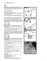
2. Rotate the cutter block so that one of the knives is at top dead centre.
Note:
A knife is at top dead centre when it is at its highest point during the
rotation. See
Fig. 5.4
for illustration of a knife at top dead centre.
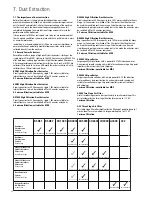
3. Place a straightedge across the out-feed table, so the end of the
straightedge is directly over the knife (
Fig. 5.5
).
4. If the out-feed table is set correctly, the straightedge will lay across
the table and barely touch the knife when it is at top dead centre (see
illustration in
Fig. 5.5
). Verify that the out-feed table height reflects this
condition.
5. If the out-feed table needs to be adjusted, release the Out-feed table lock
and adjust the height by rotating the Hand-wheel that is located below
the table.
6. When you have the out-feed table properly adjusted, lock the table height
in place.
Adjusting the In-Feed Table
1. Make sure the out-feed table is adjusted as previously described.
2. Place a straightedge across the out-feed table and the infeed table.
Note:
The straight edge used must be long enough to span the full length
of both tables.
3. Release the infeed table lock and adjust the feed table flush with the out-
feed table as illustrated in
Fig. 5.5
.
The infeed table should be exactly the same height as the out-feed table.
4. Lock the feed table in place.
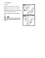
5. Set the pointer shown in
Fig. 5.2
to 0 on the depth indicator scale.
Fig. 5.4
Fig. 5.5
Fig. 5.3
A
B
Top Dead Centre
5. Operation
i
Kg
i
Kg
i
Kg
Содержание PT107
Страница 29: ...29 10 Parts List Diagrams cont ...
Страница 33: ...33 ...


