13
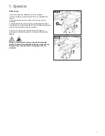
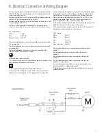
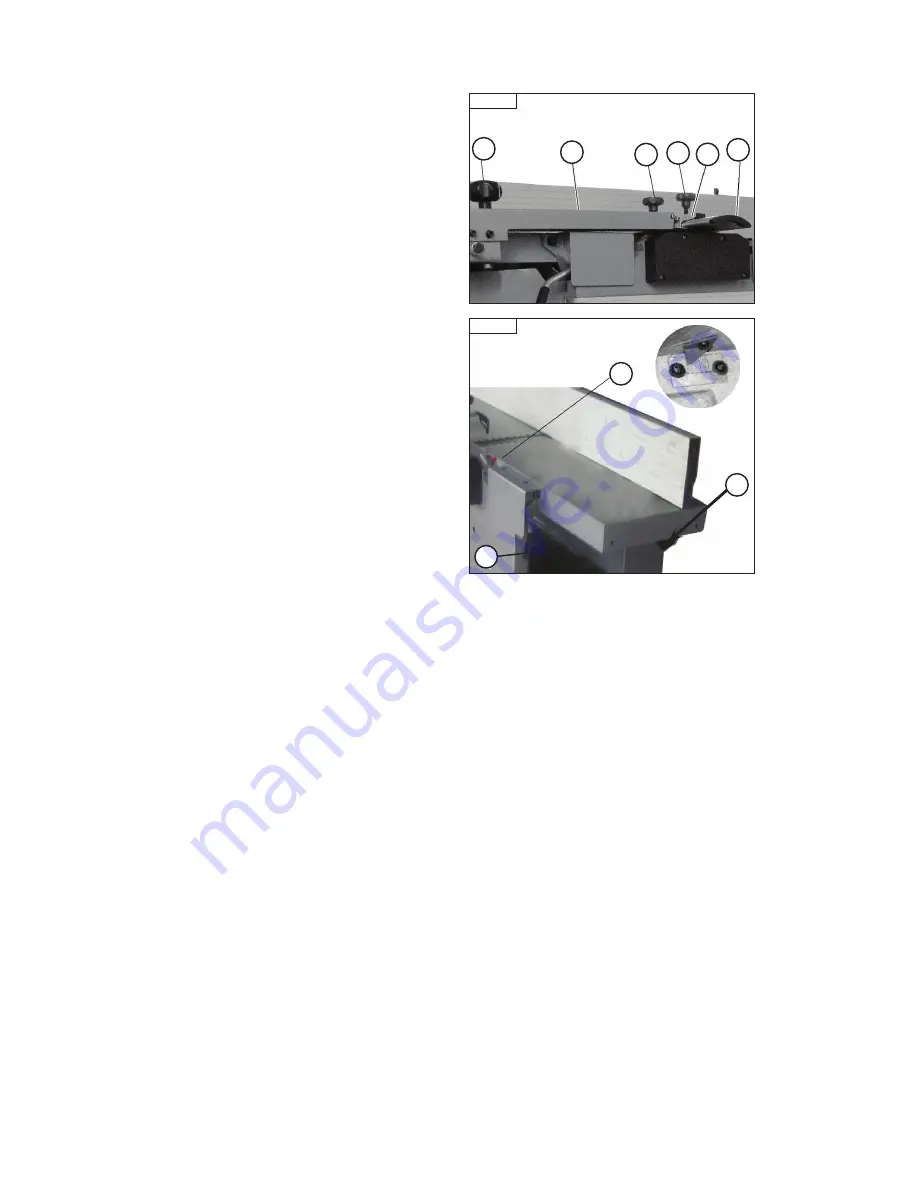
Fig. 5.1
D
B
F
E
C
A
Fig. 5.2
C
A
B
General information
Safety instructions
Before every use, check:
• All required guards are properly installed.
• All clamping screws of the blade holders are tight (minimum tightening
torque: 15 Nm).
• That you are always using sharp planer blades (minimizes the risk
of kickback).
• That the individual anti kickback guards can move freely and fall back
into their initial position after being lifted. (appllies only to thicknesser
function)
• Use auxiliary devices when working short and narrow pieces (e.g. push
stick or safety feed blocks).
Remaining risks
The following risks remain when working with the planer thicknesser
despite observing the appropriate protective measures:
• Danger of injury when changing blade.
• Observing of injury due to contact with the rotating planer cutterblock.
• Danger of injury due to ejected workpieces.
• Danger of injury due to workpiece kickback.
• Hearing danger due to high noise levels.
• Health risks due to dust emission during work especially when processing
beech and oak.
Working techniques
Permitted working techniques.
All uses deviating from those described below are considered improper uses
and are therefore not permitted.
• Planing the wide side of a workpieces.
• Planing the narrow side of a workpieces.
• Bevelling the edges of a workpieces.
Prohibited Working Techniques
The following work techniques are prohibited on the machine.
• Down-cut jointing (direction of arbor rotation same as feed direction).
• Insertion cuts (workpiece is not worked along its entire length).
• Planing of excessively warped timber.
• Thickness planing of multiple workpieces of different thicknesses.
Planer Bridge Guard
The planer bridge guard consists of the protective guard plate (A -
Fig. 5.1
),
the planer bridge guard arm (B -
Fig. 5.1
),
and support bracket (C -
Fig. 5.1
).
The height and width of the protective rail is continuously adjustable.
Height adjustment (arm tilt): set Star knob screw (D -
Fig. 5.1
).
Width adjustment: Star- knob screw (E -
Fig. 5.1
).
Star - knob screw (F -
Fig. 5.1
) is adjusted to keep the guard level.
Setting the Planer Table
The Feed Table Adjustment
Open table lock (A -
Fig 5.2
). Turn adjusting handle (B -
Fig 5.2
) until
you can see the desired value on scale (C -
Fig 5.2
) (maximum 4 mm)
Re-tighten the table lock securely.
5. Operation
Содержание PT107
Страница 29: ...29 10 Parts List Diagrams cont ...
Страница 33: ...33 ...


