background image

US FLOOR / FLOOR 

Minichiller inverter Duo 

54

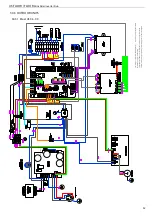
30.3.3  Mod. US 16 

GN

DR

GN

DR

R

ea

ct

or

W

V

U

Te

m

p

Se

ns

or

H

ea

tS

in

k

C

N

60

4

CN

607

R-

L3

L2

R-

L3

L2

L1

R+

R+

R

S

T

DC-

L1

L2 DC+

N

W

V

U

P

DC-

DC1

-

DC2

-

DC+

DC1

+

DC2

+

GN

D

GN

D

N

N

L1

NO

1

N

NC

1

NO

1

N

NC

1

I-

I-

I+

I+

(*

)P

re

se

nt

e

co

n

la

ge

st

io

ne

ra

pi

da

de

ll'

A

C

S

/

P

re

se

nt

 fo

rq

ui

ck

m

an

ag

em

en

tD

H

W

(#

)D

a

re

pe

rir

e

in

lo

co

 / 

O

bt

ai

n

lo

ca

lly

La

le

ge

nd

a

rip

or

ta

si

m

bo

li

no

n

ne

ce

ss

ar

ia

m

en

te

pr

es

en

ti

ne

ls

eg

ue

nt

e

sc

he

m

a

el

et

tri

co

 /

Th

e

le

ge

nd

sh

ow

s

sy

m

bo

ls

no

tn

ec

es

sa

ril

y

pr

es

en

ti

th

e

ci

rc

ui

td

ia

gr

am

Содержание FLOOR-S

Страница 1: ...Chiller and Heat Pumps US FLOOR FLOOR S HP Split Unit Inverter INSTALLATION TECHNICAL MANUAL Air to water heat pumps with high COP and HP inverter technology ...

Страница 2: ......

Страница 3: ... wasted electrical or electronic devices products should not be located together with normal domestic waste but disposed according to the current WEEE law in compliance with the European Directive 2012 19 UE Please inform yourself at your local Administration or at your reseller in case the product will be replaced with a similar one ...

Страница 4: ...CIRCUIT 11 6 11 FAN SPEED CONTROLLER 11 6 12 OPTIONAL ACCESSORIES 11 7 INSTALLATION 11 7 1 GENERALITY 11 7 2 LIFTING AND HANDLING 12 7 2 1 Indoor unit 12 7 2 2 Outdoor unit 12 7 3 POSITIONING AND MINIMUM TECHNICAL CLEARANCES 13 7 3 1 Indoor unit 13 7 3 2 Outdoor unit 13 7 4 HYDRAULIC CONNECTIONS 14 7 4 1 Hydraulic circuit 15 7 4 2 Connections positions 16 7 4 2 1 Indoor unit 16 7 4 2 2 Outdoor uni...

Страница 5: ...E AND PERIODIC CHECKS 31 13 1 ENVIRONMENTAL PROTECTION 32 14 WHEN THE UNIT GOES OUT OF SERVICE 32 15 TECHNICAL DATA 33 15 1 PERFORMANCE DATA 33 15 2 OUTDOOR UNITS 33 15 3 INDOOR UNITS 34 15 3 1 Models FLOOR FLOOR S 34 16 ELECTRIC DATA 35 16 1 MAXIMUM POWER CONSUMPTION MAX INPUT CURRENT OF THE INDOOR UNITS 06 09 35 16 2 MAXIMUM POWER CONSUMPTION MAXIMUM INPUT CURRENT OF THE INDOOR UNITS 12 16 35 17...

Страница 6: ...CEDURE TO INTERNAL PARTS 46 27 1 INDOOR UNIT 46 27 2 OUTDOOR UNIT 46 28 COMPONENTS OF INDOOR AND OUTDOOR UNITS 47 28 1 INDOOR UNIT MODEL FLOOR FLOOR S 47 28 2 INDOOR UNIT TEMPERATURE SENSORS 49 28 3 OUTDOOR UNIT 49 29 FILTER CLEANING 50 30 WIRING DIAGRAMS 50 30 1 INDOOR UNIT ELECTRIC PANEL LAYOUT 50 30 2 SINGLE PHASE INDOOR UNIT 51 30 3 OUTDOOR UNITS 52 30 3 1 Mod US 06 09 52 30 3 2 Mod US 12 53 3...

Страница 7: ...ossible inaccuracies in the manual if due to printing or transcription errors The customer shall store any updated copy of the manual or parts of it delivered by the manufacturer as an attachment to this manual The company is available to give any detailed information about this manual and to give information regarding the use and the maintenance of its own units 1 2 GRAPHIC SYMBOLS Indicates oper...

Страница 8: ...ber of directives on workplace s health and safety which include 89 391 CEE 89 686 CEE 2009 104 CE 86 188 CEE and 77 576 CEE directives Every employer shall implement such provisions and ensure that workers respect them Do not tamper with or replace parts of the equipment without the specific consent of the manufacturer The manufacturer shall have no responsibility whatsoever in case of unauthoriz...

Страница 9: ...arameters AEL 8 h e 12 h TWA 1000 ml m for each of the two components Respiratory protection For rescue and maintenance operation in storage tanks use self contained respirator apparatus The vapors are heavier than air and can cause suffocation by reducing oxygen available for breathing Eyes protection Safety glasses Protection of hands Rubber gloves Hygiene measures Do not smoke PHYSICAL AND CHEM...

Страница 10: ...oller logic for solar integration Controller logic for relaunching circulator secondary plant side optional kit installed in the factory mod GI2 5 3 MODELS FLOOR S In addition to the above indicated characteristics 1 GI2 module for solar integration management logic Management logic of the relaunching circulator secondary plant side Mixing management logic for plant side for both heating and cooli...

Страница 11: ...egrated thermal overload protection The protection class of the motors is IP X4 6 6 USER HEAT EXCHANGERS The user heat exchangers are made up of AISI 304 stainless steel braze welded plate s type The user heat exchangers are factory insulated with flexible close cell material Each evaporator is provided with a temperature sensor working as antifreeze protection that activates the circulator even i...

Страница 12: ...cing the unit it is necessary to strictly follow the rules listed in this manual to conform to all the specifications of the labels on the unit and to take any possible precautions Not observing the rules reported on this manual can create dangerous situations After receiving the unit immediately check its integrity The unit left the factory in perfect condition any eventual damage has to be quest...

Страница 13: ... not to damage the unit when handling it Removal of the packing box Cut the strap fasteners Lift the carton box upward Remove the corner pieces of polystyrene foam Remove the unit from the pallet using a suitable belt straps at least two persons equipped with suitable protective equipment for the hands and feet 7 2 2 Outdoor unit It is recommended to unpack the unit only with equipment positioned ...

Страница 14: ...re designed for outdoor installation any cover over the unit and location near trees even if they partially cover the unit is avoided in order to allow the air recirculation It is advisable to create a proper basement with a size similar to unit foot print Unit vibration level is very low it is advisable however to fit a rigid rubber band between basement and unit base frame It is also possible to...

Страница 15: ...oup and discharge valve Anti vibration joints and supports for the piping where necessary WARNING make sure that the size of the pipes shall not exceed the maximum head loss on the plant side given in the table in the Paragraph 15 3 see the available pressure head data WARNING connect the pipes to their attacks always by the way of key against key method WARNING The plant side expansion vessel inc...

Страница 16: ...nt mod FLOOR S Exchanger R410A water Key Circulator pump FS Flow switch FM Flow meter 3 bar relief valve 8 liters expansion vessel Air vent valve Y filter with metallic meshof 1000µ Temperature sensor R Optional auxiliary electric heater with double protection thermostat Check valve Manometer 0 6 bar Dial thermometer Flow regulator valve 1 Heat exchanger inlet sensor 2 Heat exchanger outlet exchang...

Страница 17: ...over to reach the terminal block B Gas connections cover C Gas connections Models Liquid pipe Gas pipe 06 1 4 SAE 1 2 SAE 09 3 8 SAE 5 8 SAE Units 12 and 16 A To reach the power supply and signal cables remove the rear side cover to reach the terminal block B Gas connections cover C Gas connections Models Liquid pipe Gas pipe 12 3 8 SAE 5 8 SAE 16 3 8 SAE 5 8 SAE 7 4 3 Drainage system connection 7...

Страница 18: ...he line of charging topping up a pressure reducer and a relief valve as indicated in the Paragraph 7 5 WARNING The water on the charging topping up pipe must be suitably pre filtered from any impurities and suspended particles Make sure that you have installed a ca rtridge filter removable as indicated in Paragraph 7 5 WARNING before proceeding to the charging topping upof the plant circuit place ...

Страница 19: ...ons of charging topping up the plugs of the air vent valves must be partially unscrewed to allow air to flow freely out of the valves The models FLOOR FLOOR S are equipped with two air vent valves one on the other DHW technical side puffer and the other on the puffer of the plant side 2 Stopper of the air vent valve When it s necessary to top up the circuit of the plant or to adjust the title of g...

Страница 20: ...mestic ut ili es Charging topping up line Water supply inlet PLANT To the plant P T P T Key Filter with extractable cartridge Loading group with pressure reducer device Discharging valve 3 bar relief valve Shut off valve Check valve Manometer 0 6 bar Dial thermometer 3 way anti scalding thermostatic valve Domestic water mixer NTC temp sensor for immersion solar collector All the components inside t...

Страница 21: ...ensor for immersion solar collector DHW recirculation temp sensor Circulator pump All the components inside the dashed line CONNECTIO NS THAT SHOULD BE DONE BY THE INSTALLER are indicated but are not supplied WARNING It is recommended to install a 3 bar re lief valve not supplied as shown in the plant diagram It is necessary to install one automatic air vent at the highest point of the plant circu...

Страница 22: ... To the plant 1 M C Water supply inlet 3 4 M D The user DHW R 3 4 M I Liquid line see Paragraph 15 3 L Gas line see Paragraph 15 3 F To the solar plant 3 4 M E From the solar plant 3 4 M FLOOR FLOOR S FLOOR FLOOR S with boiler kit I L G From the boiler 3 4 M optional H To the boiler 3 4 M optional A From the plant 1 M B To the plant 1 M C Water supply inlet 3 4 M D The user DHW R 3 4 M I Liquid li...

Страница 23: ...of piping m 25 30 30 30 B Max difference level m 15 15 20 20 Do not carry out the connections by using ordinary hydraulic pipes that might contain inside themselves residues of chips dirt or water which can damage the components of the unit and alterate the correct operation of the equipment Use only specific refrigeration copper pipes that should be provided clean and sealed at the ends Use only ...

Страница 24: ...g to the wiring diagram enclosed with the unit and according to the national and international norms in force provide equipment as general magneto thermic circuit breaker differential circuit breakers for each electric single line proper grounding for the plant etc Power supply cables the electric protection and line fuses have to be sized according to the specifications listed in the wiring diagr...

Страница 25: ...able reported in the image Use a shielded communication cable to reduce prevent interferences N Power supply cables inlet O Power supply cables outlet if present P Communication cable gateway with outdoor unit see Paragraph 7 7 3 As for the connection P the communication cable with outdoor unit it s recommend to use a shielded twisted pair multipolar cable 5x0 75mm2 and to pass it as far as possib...

Страница 26: ...analog input AI3 ST1 analog input AI4 ST9 analog input ID8 digital input CN8 AD1 ST7 analog input ID6 digital input AD2 ST8 analog input ID7 digital input DI1 ID1 digital input DI2 ID2 digital input DI3 ID3 digital input CN10 L Single phase 230Vac N NU DO1 DO1 digital output single phase 230Vac DO2 DO2 digital output single phase 230Vac DO3 DO3 digital output single phase 230Vac DO4 DO4 digital ou...

Страница 27: ...nnections listed below are standard Other connections are shown in the Control Manual of the control panel of the machine US Cod 9120523 XX Remove the mounting screws of the cover of the power supply see the paragraph 7 4 2 2 Connect the cable to the terminals inside the electric box for the models 12 and 16 you must also remove the cover and the right side panel in order to reach the terminal blo...

Страница 28: ...h 3Ph Protection device 1Ph 3Ph T I N U R O O D T U O T I N U R O O D N I Board AB Indoor unit Terminal block Outdoor unit y l p p u s r e w o P y l p p u s r e w o P INDOOR UNIT FLOOR FLOOR S OUTDOOR UNIT 06 09 12 16 WARNING Do not confuse on the terminal block of the outdoor unit between the terminals GND protective earth of the power supply with GNDR ground reference for Modbus connection Farth...

Страница 29: ...When this ELECTRIC HEATER kit is present there are 2 thermostats installed inside the single box A Manual reset thermostat Opening 90 5 C Manual rest following the procedure in the Paragraph 27 1 remove the front panel unscrew the plug casing on the on thermostats box push the red button with a suitable tool and replace the plug B Automatic reset thermostat Opening 70 4 C Differential 5 3 5 C WARNI...

Страница 30: ...na SL1 a cura dell installatore Connections Indoor Unit CB External Unit SL1 by the installer EXTERNAL UNIT INTERNAL UNIT Collegamento Unità Interna CB GI2 SL2 Connections Indoor Unit CB GI2 SL2 The picture shows a sample connection of the control system between outdoor unit US 09 model and indoor unit WALL model Fo r any versions of indoor and outdoor units the connection is the same CB controlle...

Страница 31: ...s connected Check if the anti vibration couplings exist on hydraulic pipes Check if the shut off valves of the hydraulic circuits are opened Check that the hydraulic circuit has been loaded into required pressure and vented from air Check that all the hydraulic connections are carried out correctly and that all information on the labels is respected Ensure that arrangements have been provided to d...

Страница 32: ...hooting will be easy to find In case of failure or malfunction check the type of alarm to indicate to the service center contact an authorized service center if required by the service center turn off the unit immediately without resetting the alarm require the use of original spare parts 12 SHUTDOWNS FOR LONG PERIODS Turn off the units from control panel displayed OFF Close the water tap Place th...

Страница 33: ...ing pressure and superheat and sub cooling x Check of the efficiency of circulation pump x Check the expansion tank x If the unit should be out of service for a long period discharge water from the piping and from heat exchanger This operation is necessary if during seasonal stoppages ambient temperature is expected to go down below the freezing point of the employed fluid x 13 1 ENVIRONMENTAL PRO...

Страница 34: ...ubishi Mitsubishi Type Single Rotary DC Inverter Twin Rotary DC Inverter Twin Rotary DC inverter Twin Rotary DC inverter Number 1 1 1 1 Input power in cooling mode 1 kW 1 16 2 03 2 63 3 11 Input power in cooling mode 2 kW 1 17 1 90 2 35 3 05 Input power in heating mode 3 kW 1 25 2 04 2 68 3 12 Input power in heating mode 4 kW 1 50 2 50 3 13 3 92 Refrigerant oil type quantity mL ESTER OIL VG74 480 ...

Страница 35: ...lied flow rate for DHW side L min 40 40 Minimum water flow for start up L min 3 3 Maximum capacity of the primary pump W 45 45 Maximum current of the primary pump A 0 44 0 44 Energy Efficiency Index EEI pump 0 20 0 20 Hydraulic connections inch 3 4 M 3 4 M Refrigerant circuit Liquid side connections inch 1 4 SAE 3 8 SAE 3 8 SAE 3 8 SAE Gas side connections inch 1 2 SAE 5 8 SAE 5 8 SAE 5 8 SAE Nois...

Страница 36: ...breakers and power supply cables You have to add the input power of the outdoor unit see Paragraph 15 2 to that of the indoor unit this depending on the installed electric heater kit 16 2 MAXIMUM POWER CONSUMPTION MAXIMUM INPUT CURRENT OF THE INDOOR UNITS 12 16 Model Eectric heater FLOOR 12 16 FLOOR S 12 16 A 1 1 2 W k 7 2 0 A 1 5 1 W k 9 1 0 T N E S E R P T O N Power supply 230V 1 50Hz 230V 1 50H...

Страница 37: ...fference of manometers value you should subtract the pressure drop of the 3 way valve for getting an approximate value of the available pressure head of the plant The characteristic curve corresponding to the Head pressure versus Water flow rate of the three way diverter valve whose values should be deducted at the manometric readings for verifying with sufficient accuracy the available static pressur...

Страница 38: ...ary to install on the DHW line between the instantaneous preparer and the mixers of domestic hot water of an anti scald thermostatic valve calibrated at 45 C Otherwise there is a serious risk of burning and severe scalding WARNING Make sure that there are no air bubbles in the water supply inlet otherwise the flow meter will not work properly Therefore a relief valve or an air vent should be insta...

Страница 39: ...e inlet return from the plant circuit and outlet pipes and group for forced circulation with high efficiency circulator consisting of safety group manometer integrated check and ball valves and a flow regulator 2 12 L min This group allows the charging washing maintenance of the circulator without necessarily of evacuating the plant circuit through the closing of the outlet side ball valve Main compo...

Страница 40: ...n the sufficient time has elapsed for the total evacuation of the air from the circuit close the water flow regulator valve 4 and then to the safety group 3 Open again the ball valve and reset the flow regulator valve on the desired flow rate as described in Paragraph 21 2 21 4 WASHING OF THE PLANT Close the ball valve of the outlet side 1 by rotating the knob 90 degrees clockwise and close the fl...

Страница 41: ... pressure of solar circuit bar 6 Maximum temperature C 120 Maximum solar surface m2 20 for PLAN collector 15 for collector under vacuum Solar exchange coil surface m2 0 7 Maximum head of the pump kPa 74 Maximum power of the pump W 75 Maximum absorbed current of the pump A 0 60 Energy Efficiency Index EEI pump 0 21 22 OPTIONAL DHW TECHNICAL SIDE BOILER KIT The indoor unit in all its versions can be...

Страница 42: ...1 10 9 8 7 6 5 0 6 0 8 1 0 1 2 1 4 1 6 Potenza assorbita inrefrigerazione kW Power input in cooling kW aria air 12 C aria air 7 C aria air 2 C aria air 2 C aria air 7 C aria air 10 C aria air 15 C 55 50 45 40 35 30 25 1 1 1 2 1 3 1 4 1 5 1 6 1 7 1 8 1 9 2 0 Potenza assorbita inpompa dicalore kW Power input in heating kW aria air 45 C aria air 40 C aria air 35 C aria air 30 C aria air 25 C aria air...

Страница 43: ...1 8 2 0 2 2 2 4 2 6 2 8 3 0 3 2 3 4 3 6 Potenza assorbita inrefrigerazione kW Power input in cooling kW aria air 12 C aria air 7 C aria air 2 C aria air 2 C aria air 7 C aria air 10 C aria air 15 C 55 50 45 40 35 30 25 2 0 2 5 3 0 3 5 4 0 4 5 5 0 Potenza assorbita inpompa dicalore kW Power input in heating kW aria air 45 C aria air 40 C aria air 35 C aria air 30 C aria air 25 C aria air 20 C 18 17...

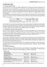
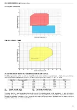
Страница 44: ...l modifications and different setting parameters of the controller with micro processor In this case contact our company for the feasibility study and evaluation of changes to be made according to your requests The maximum temperature that can be maintained at the outlet of the evaporator is 25 C In any case the maximum electrical input occurs for the heat pump operating mode at a water outlet tem...

Страница 45: ...0 99 1 05 1 12 30 14 1 0 97 0 98 1 10 1 22 40 22 3 0 965 0 97 1 14 1 25 50 33 8 0 955 0 965 1 2 1 33 CCF Capacity correction factor IPCF Input power correction factor WFCF Water flow correction factor PDCF Pressure drops correction factor The water flow rate and pressure drop correction factors are to be applied directly to the values given for operation without glycol The water flow rate correcti...

Страница 46: ...E F G H I L M N O P Q 06 09 12 16 71 134 201 268 331 394 457 524 262 333 44 114 595 1789 700 26 2 OUTDOOR UNITS US 06 09 US 12 16 SIZE mm MODELS A B C D E F H I L US 06 E 844 560 330 360 313 329 719 379 916 US 09 E 895 590 333 355 304 319 861 374 975 US 12 E US 16 E 940 633 404 448 370 392 1402 454 1024 ...

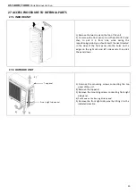
Страница 47: ...uld insert the rivets located in the sides of the front panel into the holes on the edges on the right side and left side panels then slide the panel down 27 2 OUTDOOR UNIT 1 Remove the mounting screws connecting the top panel of the unit 2 Remove the top panel 3 Remove the mounting screws connecting front right side panel 4 Push down on the front right side panel 5 Remove the front right side pan...

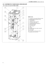
Страница 48: ...echnical side 3 Flowmeter DHW R 4 Circulator DHW R 5 Automatic air vent for plant side 6 Plate heat exchanger DHW R 7 Technical puffer tank for DHW 190 L 8 Safety pressure switch 9 Plate heat exchanger 10 3 bar relief valve 11 Y filter 12 Circulator 13 Plant side DHW technical side reverse valve 14 User s interface 15 Electric panel 16 Technical puffer tank for plant side 40 L 17 Expansion vessel ...

Страница 49: ...US FLOOR FLOOR Minichiller inverter Duo 48 MODEL FLOOR S 1 Solar group 2 Solar side circulator 3 Solar plant outlet pipe label to the solar plant 4 Solar plant return pipe label from the solar plant ...

Страница 50: ...ircuit inlet 6 DHW R secondary outlet 7 Solar coil 28 3 OUTDOOR UNIT 1 Condenser coil assy 2 Liquid separator 3 4 way valve 4 Liquid receiver 5 High pressure flow switch 6 Electronic expansion valve 7 Gas valve 8 Liquid valve 9 Compressor 10 Transducers 11 Fan 12 Fan motor 13 Fan motor support Note The figure is referring to the outdoor unit with model name US 09 and is included for illustration p...

Страница 51: ...V 30VA_ TF 2 4 pole contactor 240v coil 230V 20A_ KM1 KM2 3 Support board_ AB 4 Auxiliary power supply terminal block_ M4 5 User interface_ CB 6 Fuses for electric heaters protection_ F1 F2 F3 M2 only in case of electric heater kit installation 7 Power supply terminal block_ M1 8 Auxiliary power supply terminal block_ M3 9 Expansion board terminal block for the module GI2_ M5 ECB present only the ...

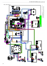
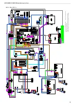
Страница 52: ...sion Terminal GI2 AB Scheda d appoggio Aux board CB Controllo principale Control board ECB Controllo Espansione GI2 Expansion control board GI2 1 KM1 Contattore resistenza ACS Contactor Resistance ACS 2 KM2 Contattore resistenza Impianto Contactor Resistance System Non installato nel quadro elettrico Not installed in the control cabinet Opzionale Optional Numero filo Number of wire Punto di massa ...

Страница 53: ...N1 GND R R Temp Sensor Heat Sink I I I I GNDR GNDR Presente con la gestione rapida dell ACS Present for quick management DHW Da reperire in loco Obtain locally La legenda riporta simboli non necessariamente presenti nel seguente schema elettrico The legend shows symbols not necessarily present in the circuit diagram ...

Страница 54: ...Temp Sensor Heat Sink I I I I GNDR GNDR Presente con la gestione rapida dell ACS Present for quick management DHW Da reperire in loco Obtain locally La legenda riporta simboli non necessariamente presenti nel seguente schema elettrico The legend shows symbols not necessarily present in the circuit diagram ...

Страница 55: ... L1 L2 DC N W V U P DC DC1 DC2 DC DC1 DC2 GND GND N N L1 NO1 N NC1 NO1 N NC1 I I I I Presente con la gestione rapida dell ACS Present for quick management DHW Da reperire in loco Obtain locally La legenda riporta simboli non necessariamente presenti nel seguente schema elettrico The legend shows symbols not necessarily present in the circuit diagram ...

Страница 56: ...g up pipe safety valve and expansion vessel not installed on water charge topping up line and on solar circuit if present manumission of the safety flow switch of the indoor unit power supply with frequency or voltage spikes that don t comply with nominal characteristics of the machine improper maintenance and failed replacement of anode faulty electrical connections improper grounding manufacture...

Страница 57: ......

Страница 58: ......

Страница 59: ......

Страница 60: ...9120488 02 12 2016 bit ly rdzwebsite ...

Отзывы: