US FLOOR / FLOOR
Minichiller inverter Duo
17
7.4.3.2 Outdoor unit
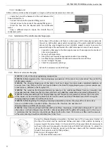
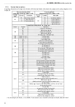
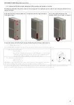
All the outdoor units have been designed in a way to use their own basement as a drain pan.
•
Locate the hole at the basement of the unit between the
finne
d coil and fan, A.
•
Connect to the hole the provided
fittin
g joint, B.
•
Connect a hose to the nozzle of the supplied
fitti
ng joint.
•
Direct the hose into the disposal place for condensate
water.
•
Keep a
suffic
ient slope to ensure the smooth
flow
of
condensate water.
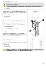
7.4.4 Installation of the relief valve discharge pipe
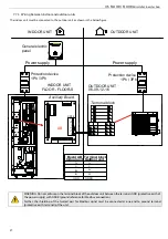
On the basis of the indoor unit there is a drain pipe in PVC, internally connected to
the unit on both safety valves outlet connec
tion
s of the plant side/DHW technical
side and of the solar integr
ation
circuit (FLOOR-S model) in order to ensure the
proper discharge of the water when the relief valve opens in case of overpressure.
•
Connect a rubber pipe to the drain pipe by means of hose pipe joint connector of
14 mm (not supplied)
• Secure it with pipe clamp.
• Direct the hose towards an appropriate loc
ation
for unloading.
• A su
ffi
cient slope should be maintained to ensure the smooth
fl
ow.
• Do not "strangle" the pipe.
• Check for proper water drainage
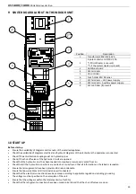
A) hole for overpressure valve discharge
7.4.5 Plant circuit water charging
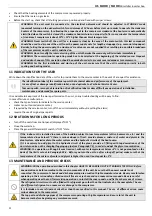
WARNING: Verify all the charging/topping-up operations.
WARNING: Before beginning the charging/topping-up operation of the plant circuit, disconnect the unit for the
electric power supply.
WARNING: The charging/topping-up of the plant circuit must always be done under controlled conditions of
pressure (max 1 bar). Make sure that you have installed on the line of charging/topping-up a pressure reducer and
a relief valve as indicated in the Paragraph 7.5.
WARNING: The water on the charging /topping-up pipe must be suitably pre-filtered from any impurities and
suspended particles. Make sure that you have installed a ca rtridge filter removable as indicated in Paragraph 7.5.
WARNING: before proceeding to the charging/topping-upof the plant circuit, place in mid-travel the 3-way valve
of the indoor unit by actuating the black lever. Restore the normal position of the black lever after finishing the
charging/topping-up operation of the plant circuit.
WARNING: Before beginning the charging /topping-up operation, unscrew the plugs of the air vent valves
(two on FLOOR/FLOOR-S models). Tighten the plugs after finishing the operation of
charging/topping-up of the plant circuit system.
WARNING: instead of using a fixed installation of the line filling /topping up, as indicated in Paragraph 7.5 , you can
alternatively use the discharge valves of which is already provided with the puffer of the indoor unit. In this case, it
is mandatory that the inlet water should be pre-filtered wi th (with at least 100 microns pre filter) and the pressure
of the water entering should be controlled (max 0.8 to 1 bar).
During the charging/topping-up opera
tio
n, the black lever of the 3-way valve (located at
the top of the valve) must be
positione
d halfway and kept in that posi
tion
by making a
pressure toward the valve interior. In this mode all the three ways (AB-A-B) communicate
with each other and consequently the plant side with DHW technical side. To unlock the
valve, a
fter
the end of charging period, push the lever down
until
the complete release
(check if the lever returns to its
lift
ed
position).
Refer to pos. 10 Paragraph 28.1.
(1) Black lever three-way valve
A
B
Содержание FLOOR-S
Страница 2: ......
Страница 57: ......
Страница 58: ......
Страница 59: ......
Страница 60: ...9120488 02 12 2016 bit ly rdzwebsite ...


