


US FLOOR / FLOOR
Minichiller inverter Duo
26
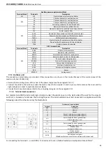
Auxiliary power supply terminal block
Terminal block
Terminals
Description
M2
N-3
Neutral conductor for electric heater
M3
LA
Phase conductor for auxiliary devices
LB
Phase conductor for auxiliary devices
LC
Phase conductor for auxiliary devices
PE
Grounding conductor for auxiliary devices
M4
N-1
Neutral conductor for auxiliary devices
N-2
Neutral conductor for auxiliary for auxiliary devices
12V
Power supply 12Vac
A11 #
Neutral for the contactor coil k1 DHW electric heater
A21 #
Phase for the K1 contactor coil DHW electric heater
TACS #
DHW electric heater thermostat
A12 #
Neutral for the K2 contactor coil GI electric heater
A22 #
Phase for the K2 contactor coil GI electric heater
TGI #
GI electric heater thermostat
GI2 # terminal block
Terminal block
Terminals
Description
M5
KCS #
Phase of solar circulator
KN #
Neutral of solar circulator
KMO #
Normally Open contact for mixing valve
KMC #
Normally closed contact for Mixing valve
KDO #
Phase of relaunching circulator
KDON #
Neutral of relaunching circulator
K1 #
Mixing valve discharge sensor
KS1 #
Solar panel collector sensor
KS2 #
Solar panel storage tank sensor
K2 #
Sensor
KPWM #
Analog output
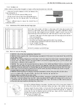
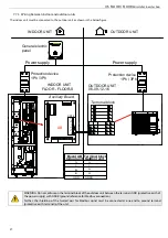
7.7.2
Outdoor unit
The connections listed below are standard. Other connections are shown in the Control Manual of the control panel of the
machine US (Cod. 9120523.XX)
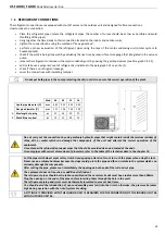
•
Remove the mounting screws of the cover of the power supply (see the paragraph 7.4.2.2.)
•
Connect the cable to the terminals inside the electric box (for the models 12 and 16 you must also remove the cover and the
right-side panel in order to reach the terminal block).
•
For electrical connections please refer to the wiring diagrams given in the paragraph 30.3.
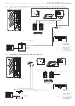
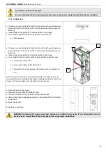
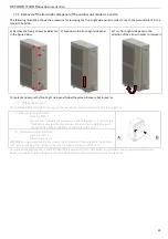
7.7.2.1
Terminal block connections
For models 6 and 09 the terminal block is located under the plastic cover on the right side of the unit for the sizes 12
and 16 it is necessary to remove the front-right panel. The terminal block must be connected in compliance with the
following notes (the schema is only for illustration).
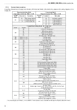
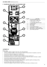
Outdoor unit terminal block
Terminal
Description
GND
Grounding
N1
Neutral
L1
Phase 1
L2
Phase 2 (only for three-phase systems)
L3
Phase 3 (only for three-phase systems)
NO
Power supply (230V AC) general alarm
(closed if the alarm is on)
N
Neutral
NC
Power supply (230V AC) general alarm
(closed if the alarm is off)
I+ / I-
Modbus Slave
Wiring with indoor unit
R+ / R-
Modbus Master
Wiring with indoor unit
GNDR
GND reference signals
(Modbus reference mass for connection with indoor unit)
For connecting the terminals I-, I+ and GNDR, t’s recommend to use a shielded twisted-pair multipolar cable 5x0.75mm
2
.
Содержание FLOOR-S
Страница 2: ......
Страница 57: ......
Страница 58: ......
Страница 59: ......
Страница 60: ...9120488 02 12 2016 bit ly rdzwebsite ...


