background image

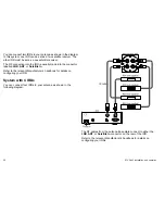
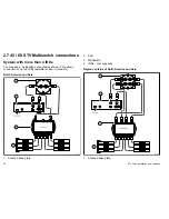
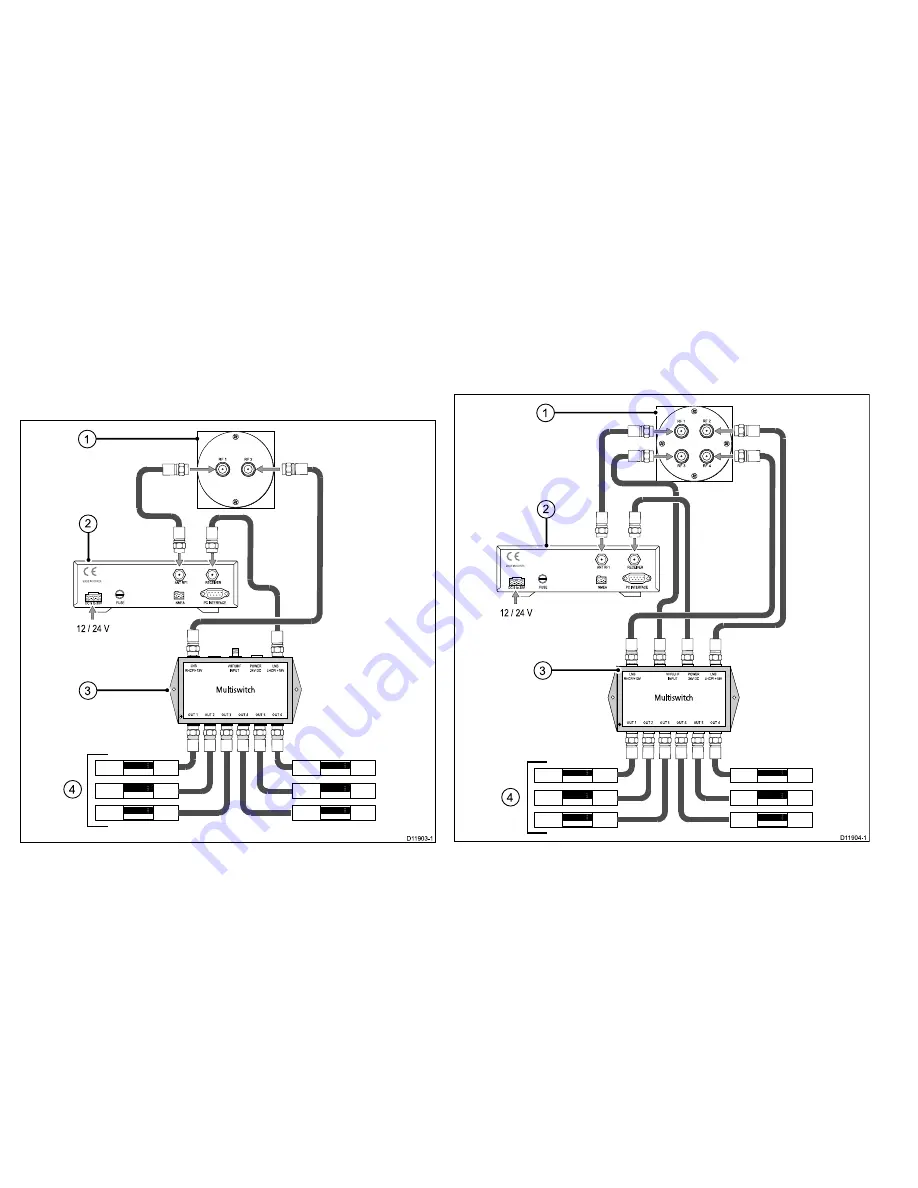
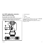
2.7 45 / 60 STV Multiswitch connections

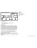
System with more than 4 IRDs

You may use a multiswitch connected as shown. This allows
connection of up to 6 IRDs (satellite receiver / decoders).

North America and Asia

1

4

D11903-1

OUT 5

OUT 2

OUT 3

OUT 4

OUT 1

OUT 6

Multiswitch

LNB

RHCP/+13V

VHF/UHF

INPUT

POWER

24V DC

LNB

LHCP/ +18V

RF 2

RF 1

A

NT RF1

FUSE

NMEA

PC INTERFACE

RECEIVER

-

+

-

+

M

ADE IN KOREA

DC 9 to 30V

12 / 24 V

3

2

1.

Antenna base plate

2.

ACU

3.

Multiswitch

4.

IRDs – (not supplied)

Regions outside of North America and Asia

Vert

Hor

Vert/mod

5-50 kHz

Hor/mod

OUT 5

OUT 2

OUT 3

OUT 4

OUT 1

OUT 6

Multiswitch

RF 2

RF 1

RF 4

RF 3

OUT 5

OUT 2

OUT 3

OUT 4

OUT 1

OUT 6

Multiswitch

LNB

RHCP/+13V

VHF/UHF

INPUT

POWER

24V DC

LNB

LHCP/ +18V

1

3

4

A

NT RF1

FUSE

NMEA

PC INTERFACE

RECEIVER

-

+

-

+

M

ADE IN KOREA

DC 9 to 30V

12 / 24 V

2

D11904-1

1.

Antenna base plate

22

STV Gen2 installation and operation

Содержание STV Gen2

Страница 1: ...STVGen2 Satellite T elevision Systems Installation and operation 37 45 and 60STVGen2 models STV Gen2 installation and operation...
Страница 2: ...mpany names referenced herein are used for identification only and are the property of their respective owners This product is protected by patents design patents patents pending or design patents pen...

Страница 3: ...ions 22 2 8 Installation Mounting 23 Chapter 3 System operation and setup 27 3 1 Introduction 28 3 2 Getting started 28 3 3 Setup using the ACU 30 3 4 Applying factory default values 37 3 5 System inf...
Страница 4: ...he connectors underneath the antenna base plate when moving the unit Do NOT use these connectors to lift the unit Caution Remove transit packing Before installing or operating the product open the ant...

Страница 5: ...date the region information using your control unit ACU or a PC running the GUI software Ensure that your satellite receivers IRDs will operate and receive DVB broadcasts at your new location Importan...

Страница 6: ...quirement for ferrites on non Raymarine cables If your Raymarine equipment is to be connected to other equipment using a cable not supplied by Raymarine a suppression ferrite MUST always be attached t...

Страница 7: ...tions on page 13 2 3 System options on page 17 2 4 Dual RF STV systems on page 17 2 5 Quad RF STV systems on page 19 2 6 37STV multiswitch connection America and Asia only on page 21 2 7 45 60 STV Mul...

Страница 8: ...ng the ACU to a personal computer for system set up and diagnostics Documentation Installation operating instructions mounting template CD containing Software for running the STV Graphical User Interf...

Страница 9: ...uns Note System performance will be reduced if supplied cables are extended If the RF cable supplied as standard is not long enough a 98 ft 30 m cable is available from your Raymarine dealer part numb...

Страница 10: ...nal tracking accuracy 37 and 60 STV Gen2 models These have a built in GPS receiver for improved tracking accuracy 45 STV This can be connected to an NMEA 0183 compatible GPS receiver using the connect...

Страница 11: ...cure cables in place using tie wraps or lacing twine Coil any extra cable and tie it out of the way Where a cable passes through an exposed bulkhead or deckhead use a suitable watertight feed through...

Страница 12: ...minimum requirement for the path to ground bonded or non bonded is via a flat tinned copper braid with a 30 A rating 1 4 inch or greater If this is not possible an equivalent stranded wire conductor m...

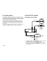
Страница 13: ...connector on the ACU must be connected to the RF1 connector on the antenna base plate 2 4 Dual RF STV systems Connecting a basic system connects to Television M onitor not supplied IRD not supplied A...

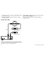
Страница 14: ...E RECEIVER M ADE INKOREA IRD2 not supplied RF cable Antenna base plate ACU Power in D11732 1 RF 2 RF 1 You can connect two IRDs to your antenna as shown in the diagram In this system one IRD can be se...

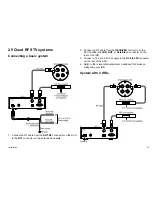
Страница 15: ...ACU to the RF1 connector on the antenna base plate 2 Connect an RF cable from the RECEIVER connector on the ACU to either the LNB ANT or Satellite In connector on the rear of the IRD 3 Connect a 12 V...

Страница 16: ...our IRD System with 4 IRDs You can connect four IRDs to your antenna as shown in the following diagram IRD1 not supplied ANTRF1 FUSE NMEA PC INTERF ACE RECEIVER MADE IN KOREA RF 2 RF 1 RF 4 RF 3 IRD2...

Страница 17: ...D11903 1 OUT5 OUT2 OUT3 OUT4 OUT1 OUT6 Multiswitch LNB RHCP 13V VHF UHF INPUT POWER 24VDC LNB LHCP 18V RF 2 RF 1 ANTRF1 FUSE NM EA PC INTERFACE RECEIVER M ADE INKOREA DC 9 to 30V 12 24 V 3 2 1 Antenn...

Страница 18: ...RF1 FUSE NM EA PC INTERFACE RECEIVER M ADE INKOREA DC 9 to 30V 12 24 V 3 2 1 Antenna base plate 2 ACU 3 Multiswitch 4 IRDs not supplied Regions outside of North America and Asia V ert Hor V ert mod 5...

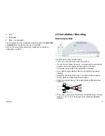
Страница 19: ...e water the maximum recommended height is one not exceeding half the length of the boat It is as near as possible to the centerline of the boat On a rigid mounting platform that is not subject to exce...

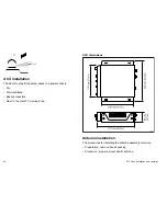
Страница 20: ...accessible Near to the main TV viewing area ACU dimensions 228 mm 9 0 in 55 mm 2 2 in 185 mm 7 3 in D11550 1 217 mm 8 5 in 178 mm 7 0 in Antenna installation The procedures for installing the antenna...

Страница 21: ...inch es 228 6 mm 9 inch es 114 3 mm 4 1 2 inc hes 114 3 mm 4 1 2 inc hes A nt e nn a B as e U ni t Te m pl at e D11451 1 3 Drill four 10 mm holes in the positions indicated Dri ll hol e 10 mm 4 10 inc...

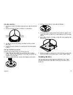
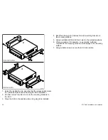
Страница 22: ...unting brackets to the ACU 3 Place the ACU in the position where it is going to be installed 4 Mark the 2 fixing hole positions for each mounting bracket on the mounting surface 5 Using a suitable dri...

Страница 23: ...3 2 Getting started on page 28 3 3 Setup using the ACU on page 30 3 4 Applying factory default values on page 37 3 5 System information on page 38 3 6 Checking system power on page 38 3 7 Skew angle...

Страница 24: ...sed to do so by the satellite provider Note The satellite names shown on the ACU screen are dependent on geographic location and therefore may be different to the names in this manual Note Vertical an...

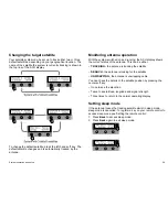
Страница 25: ...a operation With the system switched on and running the ACU display shows the current status of the antenna This can be either TRACKING the antenna is tracking the satellite SEARCH the antenna is look...
Страница 26: ...required setup screen For some setup functions you also use the PREV and NEXT soft key to select a particular value For example when setting default satellites you use PREV or NEXT cycle through the...

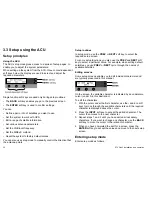
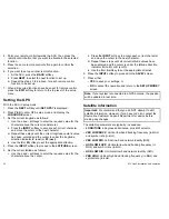
Страница 27: ...ain in setup mode or NO to re initialize the system and return to operational mode Setting the default satellites Use this procedure to set either two or three default satellites 1 Carry out the Enter...

Страница 28: ...he LATITUDE screen 5 Set the current latitude as follows i Use the and softkeys to enter the required value for the character above the cursor ii Press the INPUT soft key to accept each correct charac...

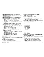
Страница 29: ...T softkey to cycle through to the EDIT SAT INFO screen 2 Press YES to enter the edit mode A satellite name edit screen is displayed 3 Use PREV or NEXT to cycle through the available satellites 4 To ed...

Страница 30: ...pplies WRS while antenna is searching for satellite OFFSET DIFF Applies Offset Difference Editing antenna parameters 1 Carry out the Enter setup mode procedure to display the SET SAT PAIR screen 2 Pre...

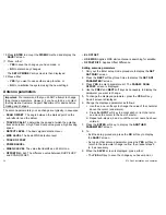
Страница 31: ...key to scroll to SINGLE 2 Press SELECT to display the LOCAL FREQ edit screen 3 Set the required frequency as follows i Use the and soft keys to change the value of the character above the cursor unde...

Страница 32: ...enables you to manually step the antenna to the required horizontal and vertical directions Setting antenna go position 1 Carry out the Enter setup mode procedure to display the SET SAT PAIR screen 2...

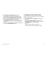
Страница 33: ...ngle is displayed on the top line 7 To leave the antenna move step mode press the EXIT soft key to return to the ANT MOVE STEP screen 3 4 Applying factory default values Use this procedure to return a...

Страница 34: ...in setup mode 1 Press the NEXT softkey to cycle through the options until the VIEW POWER screen is displayed The following information is displayed sequentially ACU POWER ANT POWER antenna power IRD p...

Страница 35: ...ttings are For the USA 0 For the EU 8 To set the skew angle 1 Ensure that all power to the system is switched off 2 Remove and retain the bolts and washers securing the antenna dome 3 Remove the anten...

Страница 36: ...cal User Interface GUI software is provided on the CDROM supplied with your system components When installed on a Personal Computer PC it enables you to operate your antenna system from the computer T...

Страница 37: ...Chapter 4 Maintenance and troubleshooting Chapter contents 4 1 Maintenance on page 42 4 2 Troubleshooting on page 42 4 3 Raymarine customer support on page 44 Maintenance and troubleshooting 41...

Страница 38: ...corrosion 4 2 Troubleshooting Your Raymarine product has been subjected to comprehensive test and quality assurance programs prior to packing and shipping However should the product develop a fault re...

Страница 39: ...reduce signal quality or cause the antenna not to work 6 Multi switch interference If you have multiple IRD s connected to your system make sure that you are using an ACTIVE not PASSIVE multi switch 7...

Страница 40: ...are application version You can obtain this product information using the menus within your product Checking serial numbers software versions Use this procedure to see product serial numbers and softw...

Страница 41: ...Chapter 5 Satellite information Chapter contents 5 1 Satellite providers on page 46 Satellite information 45...

Страница 42: ...OT234KW Astra AST01EH1 Astra AST01FH1 Astra AST01EV1 France Hotbird HOT234KS Hotbird HOT234KW Astra AST101GKU Spain Primary Astra AST01GKU Secondary limited channels Hispasat HIS01AKS Hispasat HI01CKS...

Страница 43: ...Hotbird HOT234KW Satellite providers United States of America Satellites NIMIQ1 NIM001KB NIMIQ2 NIM002KB EchoStar 3 ECH003KB EchoStar 6 8 ECH008KB EchoStar 7 ECH007KB EchoStar 1 2 ECH001KB DIRECTV DT...

Страница 44: ...to 70 C 13 F to 158 F Relative humidity max 95 Conformance CE Conforms to EU Directive 2004 108 EC System performance Frequency Ku band 10 7 to 12 75 GHz Minimum EIRP 50 dBW Azimuth range 680 Elevatio...

Страница 45: ...to 30 V dc Power consumption 30 W typical 50 W max Dimensions Satellite antenna unit 70 cm x 72 cm 27 5 in x 28 3 in Antenna dish diameter 60 cm 23 6 in Antenna control unit 17 8 cm x 21 7 cm x 5 4 cm...

Страница 46: ...Roll and pitch response rate 45 per second Turn rate 45 per second Technical specification Discover other marine electronics navigation on our website...

Отзывы: