background image


51 


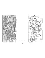
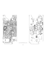
Fig.6-5 CPU PCB Layout (Rear View) 


Содержание RAY 210VHF

Страница 1: ...RAY 210VHF VHF RADIOTELEPHONE VHF RADIOTELEPHONE VHF RADIOTELEPHONE VHF RADIOTELEPHONE OPERATION MANUAL OPERATION MANUAL OPERATION MANUAL OPERATION MANUAL...

Страница 2: ......

Страница 3: ......

Страница 4: ......

Страница 5: ...per handling or use It is the user s responsibility to exercise common prudence and navigational judgment and this device should not be relied upon as a substitute for such prudence and judgment Rayma...

Страница 6: ......

Страница 7: ...L CONNECTIONS 8 2 4 1 DC Power Connections 9 2 4 2 External Speaker Connections 10 2 4 3 Antenna Connections 10 2 4 4 Antenna Mounting Suggestions 10 2 4 5 Grounding 11 SECTION 3 OPERATIONS 3 1 INTROD...

Страница 8: ......

Страница 9: ...27 4 2 3 APC Circuit 27 4 2 4 Antenna Monitoring Circuit 27 4 3 PLL CIRCUIT OPERATION 27 SECTION 5 MAINTENANCE 5 1 GENERAL 30 5 1 1 How to contact Raymarine 30 5 2 PREVENTATIVE MAINTENANCE 31 5 3 ALIG...

Страница 10: ......

Страница 11: ...annel designations as defined by International Telecommunication Union Canadian Channels Channel designations as defined by the DOC Weather Channels Channels for routine and emergency weather informat...

Страница 12: ......

Страница 13: ...e 1 2 EQUIPMENT FEATURES The RAY210 is designed and manufactured to provide ease of installation and operation with excellent reliability The important built in features of the equipment are listed be...

Страница 14: ...channel number indicated on the LCD digital display 9 Quick channel 16 or 9 key to instantly switch to emergency channel 16 9 10 Full 25 watts RF output power to the antenna port with protective circ...

Страница 15: ...KHz for 3KHz deviation Spurious Harmonic greater than 70dB below carrier power Antenna Impedance 50 ohms Receiver Channel 93 Includes 10 WX Channels Frequency Range 156 025 to 163 275MHz in 25KHz incr...

Страница 16: ...10 111 Mechanical Requirement 1 Cabinet Front ABS Rear Die Cast 2 Keyboard Silicon Rubber 3 Display Custom LCD EL Backlit LCD 4 External Hardware Non Corrosive and porous metal shall be used 5 Externa...

Страница 17: ...y event that it becomes necessary in the future to return the unit for service 2 2 EQUIPMENT SUPPLIED The following is a list of the standard equipment include with your RAY210 model Description Part...

Страница 18: ...to the rear panel connectors 4 The transceiver should be located near a power source 5 The selected location should be far enough away from devices that may cause interference such as motors and gener...

Страница 19: ...7 Figure 2 2 Outline and Mounting Dimensions...

Страница 20: ...o into a console when ordering and using the optional RAY 210 Console Mounting Kit Product Code M92803 The Console Mounting kit is available from your Raymarine dealer 2 4 ELECTRICAL CONNECTIONS Figur...

Страница 21: ...In most cases this length should be adequate enough to reach the DC power source If additional wire length is required the cable can be extended by adding more cable as necessary However for power cab...

Страница 22: ...Connect the YELLOW wire and GREEN wire with the speaker The internal speaker and the external speaker will sound simultaneously 2 4 3 Antenna Connections The coaxial cable to your VHF antenna is inte...

Страница 23: ...f power loss over the entire cable length Keep the coaxial cable between the radio and antenna as short as possible 2 4 5 Grounding While special grounding is not generally required to VHF radioteleph...

Страница 24: ...LS AND LCD DISPLAY Refer to Figure 3 1 for familiarization with the controls and mode display 3 2 1 Controls 1 On Off and Volume Control This control switches the RAY210 on and off and controls the vo...

Страница 25: ...Power setting mode press FUNC then 1 25 1W will be displayed on the LCD DWX mode press FUNC then DWX DWX will be displayed on the LCD MEM mode press FUNC then MEM MEM will be displayed on the LCD Inte...

Страница 26: ...yed on the LCD and your RAY210 will apply approximately 1 watt of power to the antenna during transmit operation When 1W is not displayed on the LCD the radio is set to provide 25 watts of power to th...

Страница 27: ...n memory then return to the previously selected channel 10 INTL International key This key causes the synthesizer to program international frequencies and illuminates the INTL symbol on the LCD To cha...

Страница 28: ...radio will remain on that channel If no signal is present when the Select Scan is deactivated the radio will revert to the channel in use prior to the selection of the Select Scan Mode When the radio...

Страница 29: ...nsitivity is set high To reduce receiving sensitivity press D L key When at low sensitivity setting DESENS11 is displayed on the LCD Note When your radio is interfered with by pagers land mobile and T...

Страница 30: ...18 Figure 3 1 Layout of Controls and Connectors...

Страница 31: ...power source is cut off 26 Check on antenna condition Antenna condition open short is checked while 25 watts TX output power is transmitted If any defect is detected An is displayed on the LCD with 7...

Страница 32: ...display when the FUNC key has been pressed to operate a secondary key function The secondary key functions are as follows SCAN 1 25 DWX MEM and INTL LCD Bar Indicator In the transmit mode the 7 bars i...

Страница 33: ...s and their frequencies To transmit and receive on channel 16 9 press the quick 16 9 key If the 16 9 is pressed again the RAY 210 will return to the previous channel NOTE Initial communication contact...

Страница 34: ...ate International operation 3 3 8 Selecting a Weather Channel To select and receive a weather channel press the WX key and then rotate the channel selector switch to the desired channel 0 9 Refer to t...

Страница 35: ...ons Yes Yes 15 156 750 156 750 Environmental 16 156 800 156 800 156 800 Emerg Calling Yes Yes 17 156 850 156 850 156 850 State Controlled Yes Yes 18 156 900 156 900 161 500 Com l Yes Yes 19 156 950 15...

Страница 36: ...56 825 77 156 875 156 875 156 875 Port Operations Yes No 78 156 925 156 925 161 525 Non Com l Yes Yes 79 156 975 156 975 161 575 Non Com l Yes Yes 80 157 025 157 025 161 625 Non Com l Yes Yes 81 157 0...

Страница 37: ...s have been removed by a pair of crystal filters FIL101 the 1st intermediate frequency signal generated in the 1st mixer is amplified at the 1st IF AMP Q30 4 1 4 2nd Intermediate Frequency Circuit The...

Страница 38: ...requency power amplifier IC 305 to drive the speaker With the amplifier circuit IC6 Q8 Q10 which drives the microphone speaker it is possible to monitor the receiving tone heard from the microphone sp...

Страница 39: ...monic waves the amplified transmitting output power is outputted as an antenna output power via a split line on the PC board pattern and an antenna monitoring circuit composed of D311 and D312 After b...

Страница 40: ...28 Fig 4 1 Block Diagram RF PCB...

Страница 41: ...29 Fig 4 2 Block Diagram CPU PCB...

Страница 42: ...ext 2333 or 603 647 7530 ext 2333 UK Rest of the World 44 23 9269 3611 ext 2029 service admin raymarine com Many Raymarine accessory items and parts are available through your authorized Raymarine dea...

Страница 43: ...dirt or corrosion 3 The radio front panel should be cleaned with a tissue or a soft non abrasive cloth Care should be exercised when cleaning any plastic surface to prevent scratching especially the...

Страница 44: ...tortion Meter 10 Toggle Switch for use as a PTT switch 11 Coaxial Switch for TX RX Antenna switching 5 3 2 PLL Adjustment TRANSMITTER RECEIVER 1 Connect the power supply 13 6V 10A to the power line an...

Страница 45: ...eviation meter 2 8 kHz 3 2 kHz 5 3 5 Power Output Adjustment 1 Connect an RF power meter to the antenna connector through the coupler Key to transmit and adjust RV1 and RV2 on the RF Board as shown in...

Страница 46: ...and while holding turning the power on This should be performed anytime a component or PCB within the radio is replaced This function will clear the RAY210 memory and will return it to its factory se...

Страница 47: ...utput of ceramic filter FIL101 i Check 21 6MHz output of first IF amplifier Q30 j Check 455 kHz signal from ceramic filter FIL3 k Failure of VCO circuit Q13 Q15 Q17 and or PLL IC9 l Defective CPU IC1...

Страница 48: ...ut from IC1 If it checks good check the triple P type network component L1 L2 C3 etc and antenna switching diode D2 If not good then check the voltage level outputs of the drive amplifiers Q3 and Q4 a...

Страница 49: ...1 C113 Ceramic 8pF 3 C130 138 145 Ceramic 10pF 1 C110 Ceramic 15pF 2 C10 34 Ceramic 10pF UJ 1 C114 Ceramic 18pF 1 C142 Ceramic 33pF 4 C28 95 144 146 Ceramic 27pF 1 C29 Ceramic 39pF 1 C156 Ceramic 47pF...

Страница 50: ...2SC1623 1 Q25 Transistor 2SC3123 1 Q30 Transistor 2SB798 1 Q32 Transistor 2SK508 1 Q15 Transistor DTC114EKA 5 Q5 12 20 31 34 Transistor DTA143EKA 1 Q6 Resistor Resistor 1 ohm 1 4W 1 R463 Resistor 10k...

Страница 51: ...il 1ST 2 L38 39 Coil LK2125R12K 1 L8 Coil LK21251ROK 1 L19 Coil LK21252R2K 1 L17 Coil LK21254R7K 2 L312 313 Coil LK21256R8K 1 L16 Coil LK2125100R 1 L18 Coil LK2125100K 3 L13 14 15 Line Filter ELKF101F...

Страница 52: ...riable resistor 10k ohm 4 RV2 3 4 5 Variable resistor 3k ohm 2 RV1 6 Connector 52559 3177 1 J101 Connector IL S 6P S2TS EF 1 J104 Connector IL S4P S2TS EF 1 J103 Connector IL S 2P S2TS EF 1 J107 Conne...

Страница 53: ...istor 2SA1298 1 Q9 Transistor 2SC1623 2 Q3 7 Transistor 2SD1767 4 Q4 5 10 11 Transistor DTC114EKA 3 Q1 2 8 Transistor DTC343TK 1 Q6 Resistor Resistor 10 ohm 3226 1 R64 Resistor 22 ohm 3226 1 R14 Resis...

Страница 54: ...1 IC1 IC BR93LC56AF 1 IC2 IC M51951AML 1 IC3 ICTA78L05F 1 IC4 IC LM2092NS 1 IC5 IC NJM386M 1 IC6 Miscellaneous Switch SKQMAL 15 S1 2 3 4 5 6 7 8 9 10 11 12 13 14 15 Filter ELKF101FA 1 Crystal 4 91MHz...

Страница 55: ...43 6 2 RAY210 ASSEMBLY DRAWING...

Страница 56: ...3 VOL SWITCH 1 G623760 14 ANTENNA CONNECTOR 1 O RING 1 EARTH RING 1 HEXAGON NUT 1 PWR CONNECTOR 1 O RING 1 NUT PWR 1 GASKET SPACER 2 SPACER FIX 2 G623760 9 RUBBER INNER FIX 2 RUBBER OUTER FIX 2 KNOB S...

Страница 57: ...45 6 3 SCHEMATIC DIAGRAM Fig 6 1 Schematic diagram RF PCB...

Страница 58: ...46 Fig 6 2 Schematic diagram CPU PCB l...

Страница 59: ...47 Fig 6 2 Schematic diagram CPU PCB 2...

Страница 60: ...48 Fig 6 3 RF PCB Layout Top View...

Страница 61: ...49 Fig 6 4 RF PCB Layout Rear View...

Страница 62: ...50 Fig 6 5 CPU PCB Layout Top view...

Страница 63: ...51 Fig 6 5 CPU PCB Layout Rear View...

Страница 64: ...52...

Страница 65: ...calls to other vessels to 30 seconds If you receive no reply wait 2 minutes then try again Keep communications brief and avoid chit chat Never transmit false distress and never use profanity on the a...

Страница 66: ...lid ship station license under the following conditions only i Except for safety purposes the hand held transceivers must be used only to communicate with the ship station with which it is associated...

Страница 67: ...d may communicate with vessels or when aboard a vessel may communicate with other vessels or coast stations NOTE A Marine Utility Ship license will not be authorized The station operates under the rul...

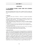
Страница 68: ...adcast Calling Channel 16 Working Channel If you wish to establish communications with another station And you know which working channel the station is monitoring Then initiate the call directly on t...

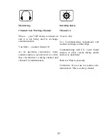
Страница 69: ...mploy a second receiver so that they can monitor a working channel and channel 16 simultaneously Intership Safety Channel 6 Vessels Any Use Communicating navigational and weather warnings to other shi...

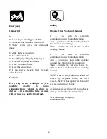
Страница 70: ...t to channel 22 as directed Navigation Channel 13 Vessels Any Use Safety communications pertaining to the manoeuvring of vessels or the directing of vessel movements Primarily ship to ship and seconda...

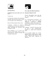
Страница 71: ...ce Seaway and designated major ports Non commercial Boat Operations Channels 9 68 69 71 72 78 Vessels Recreational boats and any not used primarily for commercial transport Use communications pertaini...

Страница 72: ...tions Recreational boats are not permitted to use these channels Channel 88 not available on Great Lakes and St Lawrence Seaway Marine Operator Channels 24 25 26 27 28 84 85 86 87 88 Vessels Any Use T...

Страница 73: ...concerning the environmental conditions in which vessels operate weather sea conditions time signals notices to mariner hazards to navigation Between One way broadcast from coast to ship stations Note...

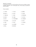
Страница 74: ...familiar words radiotelephone users usually employ the international phonetic alphabet Phonetic alphabet A ALPHA J JULIET S SIERRA B BRAVO K KILO T TANGO C CHARLIE L LIMA U UNIFORM D DELTA M MIKE V VI...

Страница 75: ...63...
Страница 76: ...2444 www raymarine com support Raymarine Ltd Raymarine Ltd Raymarine Ltd Raymarine Ltd Raymarine Inc Raymarine Inc Raymarine Inc Raymarine Inc Anchorage Park 22 Cotton Road Portsmouth Unit H Nashua P...

Отзывы: