


38
DESCRIPTION
Q'ty
Symbol
Parts No.
Elec.,47uF/25V
2
C17.19
Elec., 100
µ
F / 25V
4
C358,338,340,346
Elec., 1000
µ
F / 25V
2
C333,370
Diode
Diode M1402
1
Dl
Diode M1308
1
D2
Diode 1SS345
3
D3,311,312
Diode 1SS226
2
D9,25
Diode 1SS184
1
D303
Diode 1SS239
2
D15,16
Diode 1SV166
1
D10
Diode 1SV214
1
D11
Diode 1SV128
2
D12,14
Diode DAP202K
2
D5.317
Diode DAN202K
4
04,19,304,316
Diode DA204K
1
D310
Diode FMB-G24H
1
D24
Transistor
Transistor 2SB1185
1
Q1
Transistor 2SC4116
2
Q2,16
Transistor 2SC3357
1
Q3
Transistor 2SC4226
6
Q4,13,17,21,22,23
Transistor 2SA1298
2
Qll,33
Transistor 2SC1623
1
Q25
Transistor 2SC3123
1
Q30
Transistor 2SB798
1
Q32
Transistor 2SK508
1
Q15
Transistor DTC114EKA
5
Q5,12,20,31,34
Transistor DTA143EKA
1
Q6
Resistor
Resistor 1 ohm 1/4W
1
R463
Resistor 10k ohm 1/4W
1
R1
Resistor 150 ohm 1/4W
1
R2
Resistor 10 ohm
3
R6,15,19
Resistor 22 ohm
3
R67,114,351
Resistor 33 ohm
4
R7,18,20,107
Resistor 47 ohm
2
R182.203
Resistor 51 ohm
2
R436.442
Resistor 68 ohm
1
R104
Resistor 100 ohm
10
R16,55,64,105,109,lll,115,117,118,99
Resistor 330 ohm
2
R5,62
Resistor 470 ohm
5
R14,23,119,349,430
Resistor 680 ohm
4
R68,98,202,480
Resistor 820 ohm
1
R128
Resistor 1k ohm
9
R9,13,17,60,63,183,434,350,473
Resistor 1.2k ohm
1
R51
Resistor 1.5k ohm
3
R127,440,451
Resistor 2.2k ohm
6
R32,58,110,125,138,472
Resistor 3.3k ohm
4
R3,8,123,431
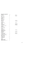
Содержание RAY 210VHF
Страница 2: ......
Страница 3: ......
Страница 4: ......
Страница 6: ......
Страница 8: ......
Страница 10: ......
Страница 12: ......
Страница 19: ...7 Figure 2 2 Outline and Mounting Dimensions...
Страница 30: ...18 Figure 3 1 Layout of Controls and Connectors...
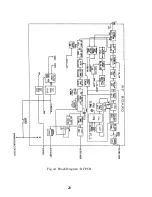
Страница 40: ...28 Fig 4 1 Block Diagram RF PCB...
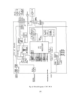
Страница 41: ...29 Fig 4 2 Block Diagram CPU PCB...
Страница 55: ...43 6 2 RAY210 ASSEMBLY DRAWING...
Страница 57: ...45 6 3 SCHEMATIC DIAGRAM Fig 6 1 Schematic diagram RF PCB...
Страница 58: ...46 Fig 6 2 Schematic diagram CPU PCB l...
Страница 59: ...47 Fig 6 2 Schematic diagram CPU PCB 2...
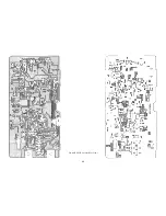
Страница 60: ...48 Fig 6 3 RF PCB Layout Top View...
Страница 61: ...49 Fig 6 4 RF PCB Layout Rear View...
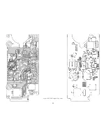
Страница 62: ...50 Fig 6 5 CPU PCB Layout Top view...
Страница 63: ...51 Fig 6 5 CPU PCB Layout Rear View...
Страница 64: ...52...
Страница 75: ...63...


