13
At the time of shipment
: n
16
9
n
Press for more than 3 sec
: n
16
n
Press for more than 6 sec
: n
9
n
Press for more than 9 sec
: n
16
9
n
(n = The Previously Monitored Channel)
This key is operative any time and will stop All Scan or Select Scan when
pressed.
5) [FUNC] (Function) Key:
When the [FUNC] key is pressed, an F will appear on the LCD to let the
operator know that a Secondary Function can be selected. To operate a
secondary function, first press the [FUNC] key, then press the desired front
panel key. To cancel a secondary function and return to the previous operating
mode, repeat the same procedure.
The function key enables the following operating modes and operations when
the associated keys are depressed:
•
All Scan Mode - press [FUNC] then [SCAN] : SCAN will be displayed on
the LCD.
•
TX Power setting mode - press [FUNC] then [1/25] :1W will be displayed on
the LCD.
•
DWX mode - press [FUNC] then [DWX] : DWX will be displayed on the
LCD.
•
MEM mode - press [FUNC] then [MEM] : MEM will be displayed on the
LCD.
•
International mode - press [FUNC] then [INTL] : INTL will be displayed the
LCD.
6) [SCAN] (All Scan) Key:
This key is used as a secondary function to activate the all scan mode. To
activate the all scan mode, press the [FUNC] key, then [SCAN]. SCAN will be
displayed on the LCD and the RAY210 will sequentially scan all USA or INTL
channels (CH 01- CH 88, See Table 3-2 page 23 and 24) except weather
channels. To cancel the scan function, press the [FUNC] key then [SCAN].
•
If signal is present on the channel that is being scanned, the scanning will
stop until the station clears. After the station clears and no signal is received for
five seconds, the scanning will resume. Pressing [SC] (scan continue) will
reactivate the scanning if the radio has stopped on a particular channel and the
operator wants to continue.
Содержание RAY 210VHF
Страница 2: ......
Страница 3: ......
Страница 4: ......
Страница 6: ......
Страница 8: ......
Страница 10: ......
Страница 12: ......
Страница 19: ...7 Figure 2 2 Outline and Mounting Dimensions...
Страница 30: ...18 Figure 3 1 Layout of Controls and Connectors...
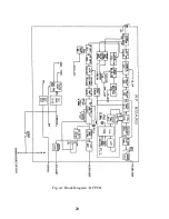
Страница 40: ...28 Fig 4 1 Block Diagram RF PCB...
Страница 41: ...29 Fig 4 2 Block Diagram CPU PCB...
Страница 55: ...43 6 2 RAY210 ASSEMBLY DRAWING...
Страница 57: ...45 6 3 SCHEMATIC DIAGRAM Fig 6 1 Schematic diagram RF PCB...
Страница 58: ...46 Fig 6 2 Schematic diagram CPU PCB l...
Страница 59: ...47 Fig 6 2 Schematic diagram CPU PCB 2...
Страница 60: ...48 Fig 6 3 RF PCB Layout Top View...
Страница 61: ...49 Fig 6 4 RF PCB Layout Rear View...
Страница 62: ...50 Fig 6 5 CPU PCB Layout Top view...
Страница 63: ...51 Fig 6 5 CPU PCB Layout Rear View...
Страница 64: ...52...
Страница 75: ...63...


