16
13) [SC] (Scan Continue) key:
During scanning mode, if a signal breaks squelch on a certain channel, the
scanning will stop on that channel. Pressing the Scan Continue [SC] key will
resume the scan operation.
14) [SS] (Select Scan) key:
Pressing this key puts the radio into the Select Scan Mode, and MEM SCAN
will be illuminated on the LCD. In this mode the RAY210 will scan only those
channels which have been stored into memory by the operator.
•
If a signal breaks squelch during the scan operation, the radio will stop on
that channel and will resume scanning only after a signal is no longer received
and the channel remains clear for five seconds.
•
If a signal breaks squelch during the scan operation and you wish to comm-
unicate with the other party, when the PTT switch is depressed, the scan mode
will deactivate and the radio will operate normally on the channel.
If a signal is present when the Select Scan is deactivated, the radio will remain
on that channel. If no signal is present when the Select Scan is deactivated, the
radio will revert to the channel in use prior to the selection of the Select Scan
Mode.
When the radio is in the Select Scan mode, the only keyboard buttons that pre-
empt the scan are [SS] and [16]. Note that two separate sets of programmed
memory channels are possible, one set of International channels and one set of
USA channels. The transmitter is inhibited in the SS mode.
15) [M1] through [M5] "quick" memory keys:
Using these keys, the operator can store up to five channels in memory for quick
and convenient access any time. To store a channel in the Ml through M5 quick
memory:
•
Select the desired channel with channel selector knob.
•
Press and hold the desired quick memory key for approximately three
seconds until two beeps are heard.
•
The memory location number will then be displayed on the LCD.
16) [RCL] (Memory Recall) key:
When this key is pressed, the RAY210 will display each of the channels that are
currently stored in memory for the Select Scan mode.
Upon completion, the radio will return to the previously selected channel.
Содержание RAY 210VHF
Страница 2: ......
Страница 3: ......
Страница 4: ......
Страница 6: ......
Страница 8: ......
Страница 10: ......
Страница 12: ......
Страница 19: ...7 Figure 2 2 Outline and Mounting Dimensions...
Страница 30: ...18 Figure 3 1 Layout of Controls and Connectors...
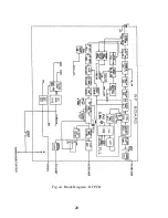
Страница 40: ...28 Fig 4 1 Block Diagram RF PCB...
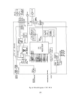
Страница 41: ...29 Fig 4 2 Block Diagram CPU PCB...
Страница 55: ...43 6 2 RAY210 ASSEMBLY DRAWING...
Страница 57: ...45 6 3 SCHEMATIC DIAGRAM Fig 6 1 Schematic diagram RF PCB...
Страница 58: ...46 Fig 6 2 Schematic diagram CPU PCB l...
Страница 59: ...47 Fig 6 2 Schematic diagram CPU PCB 2...
Страница 60: ...48 Fig 6 3 RF PCB Layout Top View...
Страница 61: ...49 Fig 6 4 RF PCB Layout Rear View...
Страница 62: ...50 Fig 6 5 CPU PCB Layout Top view...
Страница 63: ...51 Fig 6 5 CPU PCB Layout Rear View...
Страница 64: ...52...
Страница 75: ...63...


