background image

4.1 General cabling guidance

Cable types and length

It is important to use cables of the appropriate type and length

• Unless otherwise stated use only standard cables of the

correct type, supplied by Raymarine.

• Ensure that any non-Raymarine cables are of the correct

quality and gauge. For example, longer power cable runs may
require larger wire gauges to minimize voltage drop along the
run.

Routing cables

Cables must be routed correctly, to maximize performance and
prolong cable life.

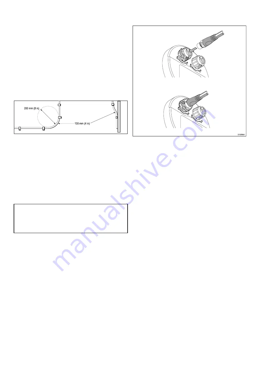
• Do NOT bend cables excessively. Wherever possible, ensure

a minimum bend diameter of 200 mm (8 in) / minimum bend
radius of 100 mm (4 in).

100 mm (4 in)

200 mm (8 in)

• Protect all cables from physical damage and exposure to heat.

Use trunking or conduit where possible. Do NOT run cables
through bilges or doorways, or close to moving or hot objects.

• Secure cables in place using tie-wraps or lacing twine. Coil

any extra cable and tie it out of the way.

• Where a cable passes through an exposed bulkhead or

deckhead, use a suitable watertight feed-through.

• Do NOT run cables near to engines or fluorescent lights.

Always route data cables as far away as possible from:

• other equipment and cables,

• high current carrying ac and dc power lines,

• antennae.

Caution: Pulling cables

Do NOT use cords or ropes, attached to cable
connectors, to pull cables through restricted
apertures (e.g. as in bulkheads), as this could
cause damage to cables.

Strain relief

Ensure adequate strain relief is provided. Protect connectors
from strain and ensure they will not pull out under extreme sea
conditions.

Circuit isolation

Appropriate circuit isolation is required for installations using
both AC and DC current:

• Always use isolating transformers or a separate power-inverter

to run PC’s, processors, displays and other sensitive electronic
instruments or devices.

• Always use an isolating transformer with Weather FAX audio

cables.

• Always use an isolated power supply when using a 3rd party

audio amplifier.

• Always use an RS232/NMEA converter with optical isolation

on the signal lines.

• Always make sure that PC’s or other sensitive electronic

devices have a dedicated power circuit.

Cable shielding

Ensure that all data cables are properly shielded that the
cable shielding is intact (e.g. hasn’t been scraped off by being
squeezed through a tight area).

4.2 Connections overview

Cable connectors are on the rear of the product.

D12056-1

The unit has 2 x SeaTalk

ng

connectors.

Connecting SeaTalk

ng

cables

1. Rotate the locking collar on the back of the unit to the

UNLOCKED position.

2. Ensure the spur cable end connector is correctly oriented.

3. Fully insert the cable connector.

4. Rotate locking collar clockwise (2 clicks) until it snaps into

the LOCKED position.

24

p70 / p70R

Содержание P70

Страница 1: ...p70 p70R Installation and operation instructions English Date 02 2014 Document number 81355 1 EN 2014 Raymarine UK Limited STBY STBY...

Страница 2: ......

Страница 3: ...s patents pending or design patents pending Fair Use Statement You may print no more than three copies of this manual for your own use You may not make any further copies or distribute or use the manu...

Страница 4: ......

Страница 5: ...n differences between Evolution and SPX systems 38 7 3 Autopilot response levels 39 7 4 Initial setup and commissioning 39 7 5 Powering the pilot controller on 40 7 6 Using the set up wizard 40 7 7 Us...

Страница 6: ...cover 94 Chapter 15 Technical support 95 15 1 Raymarine customer support 96 15 2 Viewing product information 96 Chapter 16 Technical specification 97 16 1 Viewing angle 98 16 2 Technical specification...

Страница 7: ...vent potential damage to equipment Raymarine recommends that any external equipment connected to this product also features an isolated power supply TFT Displays The colors of the display may seem to...

Страница 8: ...port its policy and ask you to be aware of how to dispose of this product Warranty registration To register your Raymarine product ownership please visit www raymarine com and register online It is im...

Страница 9: ...Chapter 2 Document and product information Chapter contents 2 1 Document information on page 10 2 2 Product overview on page 11 Document and product information 9...

Страница 10: ...display Select Transducer Set Up The term Select is used to refer to the action of selecting a menu option on a multifunction display using the touchscreen or physical controls depending on display va...

Страница 11: ...STBY STBY D13016 1 1 2 1 p70 8 button pilot control head 2 p70R Rotary pilot control head The unit has the following features 2 x SeaTalkng connections Compatible with NMEA 2000 and SeaTalk standards...

Страница 12: ...12 p70 p70R...

Страница 13: ...ge 15 3 4 Compatible autopilot systems on page 16 3 5 Software updates on page 16 3 6 Tools on page 17 3 7 Typical systems on page 17 3 8 System protocols on page 18 3 9 Warnings and cautions on page...

Страница 14: ...on It is also useful for any future additions or maintenance of the system The diagram should include Location of all components Connectors cable types routes and lengths 3 2 Pack contents All models...

Страница 15: ...ments 3 SeaTalkng Instruments 4 MOB via SeaTalk to SeaTalkng converter 5 SeaTalkng GPS receiver 6 SeaTalkng Pilot controller 7 Raymarine Multifunction displays 8 Raymarine autopilots 9 Fluxgate compas...

Страница 16: ...d and compatible multifunction display Refer to www raymarine com software for the latest software updates and the software update procedure for your product If in doubt as to the correct procedure fo...

Страница 17: ...tions that accompanied your system Example Evolution system SeaTalkng SeaT alkng SeaT alk ng 12 V 0 12 V 3 5 SeaT alkng SeaT alkng 2 1 7 6 8 D12877 1 4 9 1 Power supply for SeaTalkng 2 Evolution autop...

Страница 18: ...d within the backbone Devices that have a low draw can be powered from the network although high current equipment will need to have a separate power connection SeaTalkng is a proprietary extension to...

Страница 19: ...essel Cable entry Ensure the unit is mounted in a location which allows proper routing and connection of cables Minimum bend radius of 100 mm 3 94 in unless otherwise stated Use cable supports to prev...

Страница 20: ...e smaller vessels it may not be possible to locate the product this far away from a compass In this situation when choosing the installation location for your product ensure that the compass is not af...

Страница 21: ...eens takes you through the following Language selection Vessel type selection If a pilot controller already exists on your system then this procedure may be skipped and the p70 p70r will adopt the sam...

Страница 22: ...22 p70 p70R...

Страница 23: ...tions Chapter contents 4 1 General cabling guidance on page 24 4 2 Connections overview on page 24 4 3 Power connection on page 25 4 4 SeaTalkng connection on page 26 4 5 SeaTalk connection on page 27...

Страница 24: ...s or ropes attached to cable connectors to pull cables through restricted apertures e g as in bulkheads as this could cause damage to cables Strain relief Ensure adequate strain relief is provided Pro...

Страница 25: ...e 6 Vessel distribution panel 7 Vessel RF ground point connection Note Only applicable to products that include a drain wire on the product s power cable Thermal breaker rating 5 A if only connecting...

Страница 26: ...ore applying power to this product ensure it has been correctly grounded in accordance with the instructions in this guide 4 4 SeaTalkng connection The unit connects as part of a SeaTalkng network Exa...

Страница 27: ...r reference transducer 8 Fluxgate compass 9 Wind transducer 10 Speed transducer 11 Depth transducer 4 5 SeaTalk connection Connections to a SeaTalk network are made using a SeaTalk to SeaTalkng adapto...

Страница 28: ...28 p70 p70R...

Страница 29: ...Chapter 5 Mounting Chapter contents 5 1 Mounting on page 30 Mounting 29...

Страница 30: ...e around the cut edge until smooth 6 Drill four holes as indicated on the template to accept the securing screws 7 Peel the backing off of the gasket and place the adhesive side of the gasket onto the...

Страница 31: ...ing started Chapter contents 6 1 Pilot functions on page 32 6 2 Pilot controls on page 32 6 3 Instrument power on page 33 6 4 Display settings on page 34 6 5 Multiple data sources MDS on page 35 Getti...

Страница 32: ...y Autopilot engaged in power steering mode activated from the Mode menu Jog steer Autopilot disengaged in jog steer mode tiller drives and SeaTalk only activated whilst in Standby mode 6 2 Pilot contr...

Страница 33: ...ontroller supports the following combination button presses Combination button press Buttons Action STANDBY and AUTO Puts pilot in to Wind Vane mode 1 and 10 or 1 and 10 AutoTack in wind vane mode Aut...

Страница 34: ...all displays you wish to share Adjusting the shared brightness Shared brightness is only accessible if the display has been assigned to a network group 1 Whilst on a favorites page press the LEFT SOFT...

Страница 35: ...ftware is not available and you do NOT want the system to automatically attempt to resolve data conflicts any non compliant product s can be removed or replaced to ensure the entire system is MDS comp...

Страница 36: ...36 p70 p70R...

Страница 37: ...ystems on page 38 7 3 Autopilot response levels on page 39 7 4 Initial setup and commissioning on page 39 7 5 Powering the pilot controller on on page 40 7 6 Using the set up wizard on page 40 7 7 Usi...

Страница 38: ...Evolution system provides a number of features to improve upon the commissioning process required by existing SPX and some other autopilot systems Built in heading and attitude sensor no additional fl...

Страница 39: ...nvolves the following steps Important Before proceeding with the initial set up or commissioning of a p70 p70R ensure that your p70 p70R is running the latest software p70 p70R operation with Evolutio...

Страница 40: ...been saved 6 Select OK to complete the set up wizard Vessel hull type selection The vessel hull type options are designed to provide optimum steering performance for typical vessels It is important t...

Страница 41: ...rudder limit will be displayed with a message confirming that the rudder limit has been updated This value can be changed if required For vessels without a rudder reference transducer a default of 30...

Страница 42: ...allation environment of the EV unit and the levels of magnetic interference at the time of conducting the process Sources of significant magnetic interference may increase the time required to complet...

Страница 43: ...ng to prevent the autopilot system from completing a further automatic linearization in the future This feature is particularly useful for vessels in environments that are exposed to strong magnetic d...

Страница 44: ...44 p70 p70R...

Страница 45: ...ial setup and commissioning on page 47 8 4 Powering the pilot controller on on page 47 8 5 Using the set up wizard on page 48 8 6 Dockside calibration on page 48 8 7 Dealer settings on page 49 8 8 Adj...

Страница 46: ...hanges to the pilot response at any time by accessing the Pilot response menu from Main menu Pilot Response 1 From the Main menu highlight Pilot response and press SELECT 2 Use the UP and DOWN buttons...

Страница 47: ...autopilot system Commissioning process Check you have adhered to commissioning pre requisites Initial power on and set up Dockside calibration Dealer Settings on SeaTalk systems Set hard over time non...

Страница 48: ...e wizard all commissioning settings will be reset to default settings and you will need to complete the Dockside calibration process again 8 6 Dockside calibration The dockside calibration process mus...

Страница 49: ...pilot will now automatically move the rudder to port and then starboard 5 For vessels without a rudder reference transducer you will be asked to confirm that the rudder has turned to port by selecting...

Страница 50: ...ation Commissioning Note Sailing vessels should perform the sea trial under engine power Note The Sea trial wizard can be cancelled at any time by pressing the Standby button Warning Seatrial calibrat...

Страница 51: ...mpass heading and hold a steady course at normal cruising speed If necessary steer the vessel manually for a short time to check how the vessel steers 2 Ensure it is safe to engage the autopilot then...

Страница 52: ...t stops hunting Always ensure the lowest acceptable value is used If required the Rudder Damping setting can be adjusted from the Drive Settings menu Menu Set up Autopilot Calibration Drive Settings R...

Страница 53: ...4 9 2 Auto on page 54 9 3 Mode menu on page 55 9 4 Patterns on page 55 9 5 Track mode on page 56 9 6 Wind vane mode Sailing boats only on page 58 9 7 Power steer on page 60 9 8 Jog steer tiller pilots...

Страница 54: ...the display 3 You can return to manual steering at any time by pressing STANDBY Changing course in auto mode To change course whilst in AUTO mode 1 Use the 1 and 10 button or turn the rotary controll...

Страница 55: ...l Increment Direction Radius Circle against Distance Direction Figure 8 Radius Direction Width Height Width increment Pattern search Height increment Direction 180 turn Radius Direction Width Box sear...

Страница 56: ...route From the menu 1 Select Mode 2 Select Track The display will show the bearing to the next planned waypoint and the direction in which the vessel will turn onto the track line 3 If it is safe for...

Страница 57: ...played When the waypoint arrival warning is displayed 1 Check that it is safe to turn onto the new heading 2 If it is NOT safe or you do not want to advance to the next waypoint you can i Select CANCE...

Страница 58: ...this to True wind in the Sail Boat Settings menu Menu Set up Autopilot Calibration Sail Boat Settings Wind Type Using wind vane mode You can select Wind vane mode from either STANDBY or AUTO mode 1 St...

Страница 59: ...p70 i Press the 1 and 10 buttons at the same time to Tack to port ii Press the 1 and 10 buttons at the same time to Tack to starboard 2 Using a p70R or a p70 i Select Tack Port from the main menu to...

Страница 60: ...menu Set up Auto pilot calibration Drive settings Power steer Note In order to use Bang Bang mode a connected joystick is required the p70r rotary will only perform in Proportional mode 9 8 Jog steer...

Страница 61: ...ssigned as shortcuts Track default All vessels Pattern Power and fishing vessels Power steer All vessels Rotary only Wind vane Sailing vessels Assigning the shortcut key In order to assign a pilot mod...

Страница 62: ...62 p70 p70R...

Страница 63: ...ilot views on page 64 10 2 Graphical view on page 64 10 3 Large view on page 65 10 4 Standard view on page 65 10 5 Multiple view on page 66 10 6 2D View on page 66 10 7 Setting the pilot view on page...

Страница 64: ...teer 4 Partial compass 5 Wind direction indicator 6 Current heading Standby and Power Steer Locked heading Auto Wind Vane and Pattern 7 Heading Magnetic True The type of heading is determined by the l...

Страница 65: ...button Track default Pattern Wind Vane 10 4 Standard view The Standard view provides large sized heading data combined with data boxes which provide further information 335o Track 15 69 23 30 20 10 1...

Страница 66: ...lt Pattern Wind Vane 10 6 2D View The 2D view includes a full compass dial and data boxes for displaying information Track 30 20 10 10 20 30 Track Waypoint 17 TWS Kts Depth ft SOG Kts N E W S 050o M 1...

Страница 67: ...your chosen Pilot view displayed 1 Select Menu 2 Select Pilot View 3 Select Data Boxes 4 Select the Data box that you want to change the data for A list of available data is displayed 5 Select the rel...

Страница 68: ...68 p70 p70R...

Страница 69: ...Chapter 11 Pilot controller alarms Chapter contents 11 1 Alarms on page 70 Pilot controller alarms 69...

Страница 70: ...t mode Change course Correct course Route Complete Flagged by chart plotter navigator when the last waypoint in a route has been reached Change pilot mode Alarm name Alarm type Description Action Larg...

Страница 71: ...fail 1 not carried out Safety Alarm Autolearn has not been carried out Restart AutoLearn Alarm name Alarm type Description Action AutoLearn fail 2 Manual intervention Safety Alarm Manual intervention...

Страница 72: ...stopped Check Seatalk connections for short or open circuit Check system for Seatalk device fault SeaTalk 1 fail Alarm SeaTalk channel 1 has a communication problem Change pilot mode SeaTalk 2 fail A...

Страница 73: ...2 1 Set up menu on page 74 12 2 Autopilot calibration menu on page 74 12 3 System set up menu on page 81 12 4 User preferences menu on page 82 12 5 Simulator on page 83 12 6 Factory reset on page 83 1...

Страница 74: ...nit On Off Factory reset Delete user settings and Restore unit to factory default settings Yes No Diagnostics Information About the display and system and key beep on off setting Yes No 12 2 Autopilot...

Страница 75: ...ant upon connected autopilot system Note The drive type option is not available in systems comprising of an EV 2 and an ACU 300 Type 1 Linear ACU 200 and ACU 400 Type 2 Linear ACU 400 only Type 2 Hydr...

Страница 76: ...lot by taking hold of the wheel or tiller When you release the wheel or tiller the pilot will return to the last locked heading Note Only available on S1 S2 or S3 course computers only with drive type...

Страница 77: ...e Note If no rudder reference has been fitted you MUST ensure that adequate provision is made to prevent the steering mechanism from impacting the end stops 10 40 30 default Rudder offset This specifi...

Страница 78: ...a Off course alarm This screen determines the angle used by the OFF COURSE alarm The OFF COURSE alarm operates if the pilot strays off course by more than the specified angle for more than 20 seconds...

Страница 79: ...low the vessel to tack through into and away from the wind With gybe inhibit set to prevent you can only tack through into the wind Gybe inhibit does not effect Auto Turn Allow Gybe Prevent Gybe Wind...

Страница 80: ...Yes Align Compass Manual adjustment of the compass offset 10 to 10 179 to 180 Pilot Factory Reset Resets the autopilots course computer to factory default settings Yes No Yes No Debug Level Sets the d...

Страница 81: ...5 Brightness color group Enables synchronization of the displays brightness and color to be the same as the other units in the same group Sync brightness color This display This group Data sources All...

Страница 82: ...w rate Heading Pressure Volume Speed Kts knots MPH miles per hour KPH Kilometers per hour Distance nm Nautical miles sm Statute miles km Kilometers Depth ft Feet m Metres Fa Fathoms Wind speed Kts kno...

Страница 83: ...ilst navigating Note The simulator will NOT display any real data including any safety messages such as those received from AIS units Note Any system settings made whilst in Simulator mode are not tra...

Страница 84: ...version Temperature Volts Max volts Current Max current Run time Deviation If available About system Allows you to view information about products on the system you are using Model number Serial numb...

Страница 85: ...Chapter 13 Troubleshooting Chapter contents 13 1 Troubleshooting on page 86 Troubleshooting 85...

Страница 86: ...r to packing and shipping subjected to comprehensive test and quality assurance programs However if you experience problems with the operation of your product this section will help you to diagnose an...

Страница 87: ...causes Possible solutions Check relevant fuses and breakers Check that the power supply cable is sound and that all connections are tight and free from corrosion The system or part of it does not star...

Страница 88: ...nstrument or engine interface Check the power to the SeaTalk bus Data source e g ST70 instrument or engine interface is not operating Refer to the manufacturer s handbook for the equipment in question...

Страница 89: ...y Check that the power source is of the correct voltage and sufficient current Software mismatch on system upgrade required Go to www raymarine com and click on support for the latest software downloa...

Страница 90: ...90 p70 p70R...

Страница 91: ...Chapter contents 14 1 Routine equipment checks on page 92 14 2 Cleaning on page 92 14 3 Cleaning the display screen on page 93 14 4 Cleaning the display case on page 93 14 5 Cleaning the sun cover on...

Страница 92: ...following checks on a regular basis Examine all cables for signs of damage or wear and tear Check that all cables are securely connected 14 2 Cleaning Best cleaning practices When cleaning this produ...

Страница 93: ...ng cloth available from an opticians 14 4 Cleaning the display case The display unit is a sealed unit and does not require regular cleaning If it is necessary to clean the unit follow this basic proce...

Страница 94: ...aminants may stick to this surface To avoid damaging the monitor display clean the sun cover regularly following this procedure 1 Carefully remove the sun cover from the display 2 Rinse the sun cover...

Страница 95: ...Chapter 15 Technical support Chapter contents 15 1 Raymarine customer support on page 96 15 2 Viewing product information on page 96 Technical support 95...

Страница 96: ...0 Toll Free 1 800 539 5539 E mail support raymarine com In the UK Europe and the Middle East Tel 44 0 13 2924 6777 E mail ukproduct support raymarine com In Southeast Asia and Australia Tel 61 0 29479...

Страница 97: ...Chapter 16 Technical specification Chapter contents 16 1 Viewing angle on page 98 16 2 Technical specification on page 98 Technical specification 97...

Страница 98: ...c Current 132 mA Power consumption 1 6 W LEN Refer to the SeaTalkng reference manual for further information 3 Environmental Operating temperature 25 C to 55 C 13 F to 131 F Storage temperature range...

Страница 99: ...essories Chapter contents 17 1 Spares and accessories on page 100 17 2 SeaTalkng cabling components on page 100 17 3 SeaTalkng cables and accessories on page 101 17 4 SeaTalk accessories on page 102 S...

Страница 100: ...o make junctions in the backbone to which devices can then be connected Terminator Required at either end of the backbone Inline terminator Used to connect a spur cable directly to the end of a backbo...

Страница 101: ...erminator A06031 SeaTalkng T piece A06028 Provides 1 x spur connection SeaTalkng 5 way connector A06064 Provides 3 x spur connections SeaTalkng backbone extender A06030 SeaTalk to SeaTalkng converter...

Страница 102: ...t No Notes 3 way SeaTalk junction box D244 1 m 3 28 ft SeaTalk extension cable D284 3 m 9 8 ft SeaTalk extension cable D285 5 m 16 4 ft SeaTalk extension cable D286 9 m 29 5 ft SeaTalk extension cable...

Страница 103: ......

Страница 104: ...www raymarine com...

Отзывы: