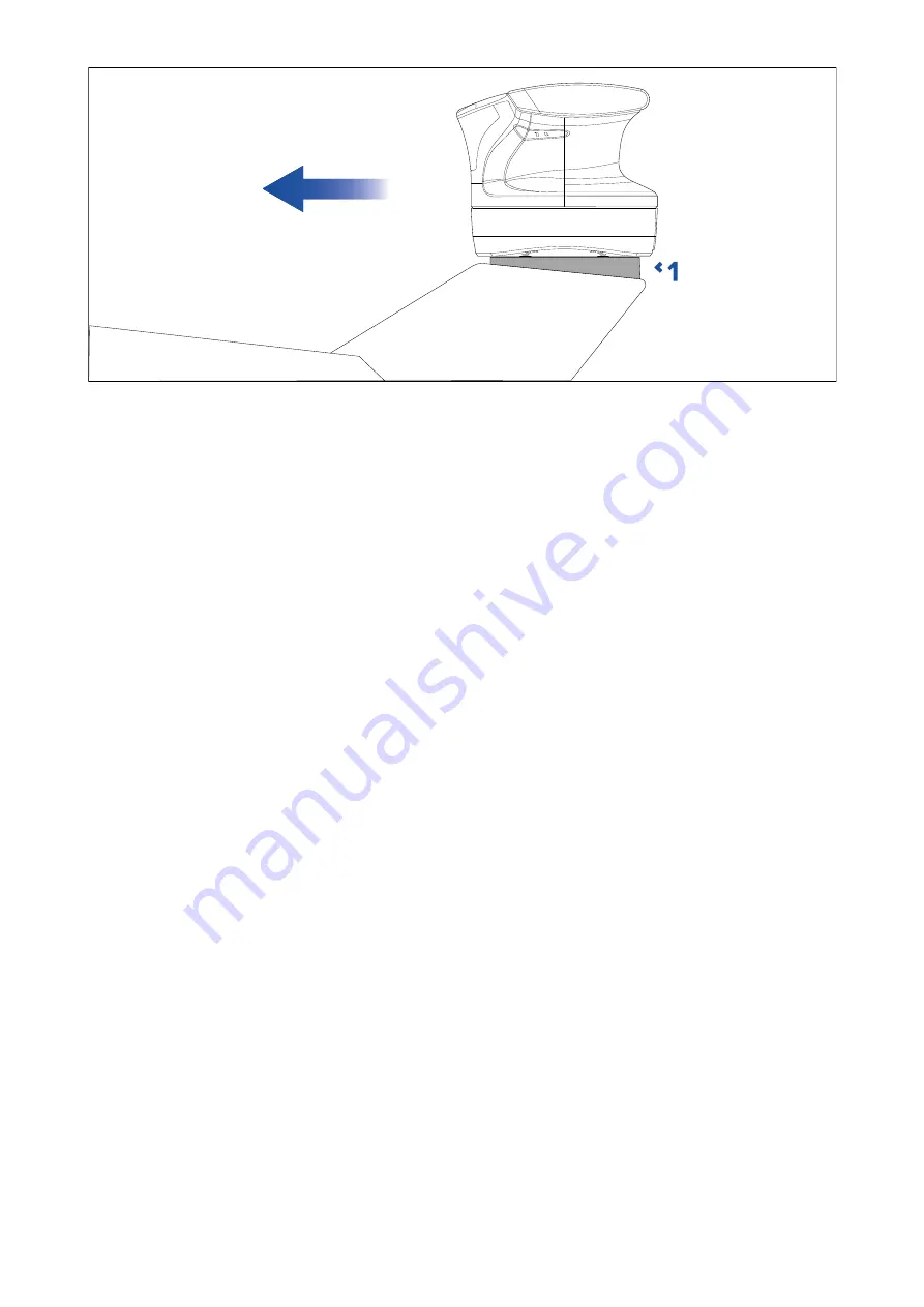
1.
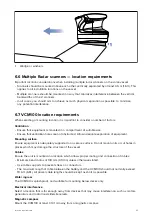
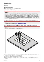
Wedge or washers
6.6 Multiple Radar scanners — location requirements
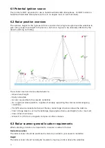
Important location considerations when installing multiple radar scanners on the same vessel.
• Scanners should be mounted above each other, vertically separated by at least 0.5 m (1.6 ft). This
applies to all installation locations on the vessel.
• Multiple scanners should be mounted in a way that minimizes interference between the vertical
beamwidths of the 2 scanners.
• In all cases, you should aim to achieve as much physical separation as possible, to minimize
any potential interference.
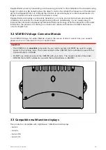
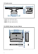
6.7 VCM100 location requirements
When selecting a mounting location it is important to consider a number of factors.
Ventilation
• Ensure that equipment is mounted in a compartment of suitable size.
• Ensure that ventilation holes are not obstructed. Allow adequate separation of equipment.
Mounting surface
Ensure equipment is adequately supported on a secure surface. Do not mount units or cut holes in
places which may damage the structure of the vessel.
Cables
Ensure the unit is mounted in a location which allows proper routing and connection of cables:
• Minimum bend radius of 100 mm (3.94 in) unless otherwise stated.
• Use cable supports to prevent stress on connectors.
• The maximum length of cable between the battery and the VCM100 should not normally exceed
19.6 ft. (6 M). All power cable lengths should be kept as short as possible.
Water ingress
The VCM100 is splashproof, and suitable for mounting below decks only.
Electrical interference
Select a location that is far enough away from devices that may cause interference, such as motors,
generators and radio transmitters/receivers.
Magnetic compass
Mount the VCM100 at least 3 ft (1 m) away from a magnetic compass.
35
Содержание CYCLONE
Страница 2: ......
Страница 4: ......
Страница 8: ...8...
Страница 15: ...Chapter 2 Document information Chapter contents 2 1 Document information on page 16 Document information 15...
Страница 20: ...20...
Страница 28: ...28...
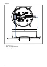
Страница 40: ...Rear exit 1 Mounting surface 2 Power and RayNet connectors 3 Power and RayNet cables 40...
Страница 42: ...42...
Страница 52: ...52...
Страница 53: ...Chapter 9 System connections Chapter contents 9 1 Typical system examples on page 54 System connections 53...
Страница 58: ...58...
Страница 59: ...Chapter 10 Power connections Chapter contents 10 1 Radar power connections on page 60 Power connections 59...
Страница 64: ...64...
Страница 69: ...Chapter 12 Operation Chapter contents 12 1 Operation instructions on page 70 Operation 69...
Страница 80: ...80...
Страница 84: ...84...
Страница 88: ......
Страница 91: ......


